


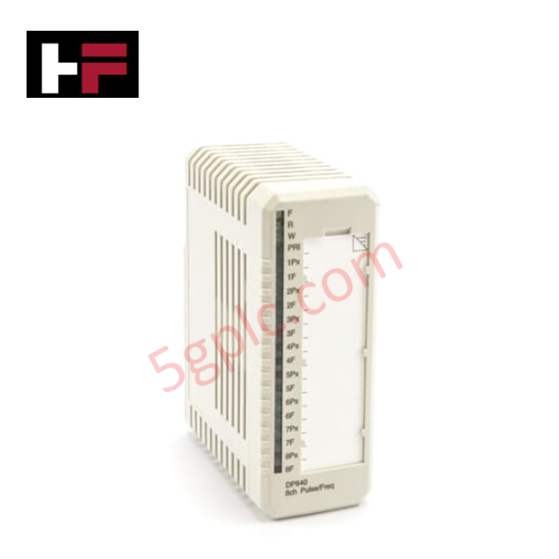
Détails du produit
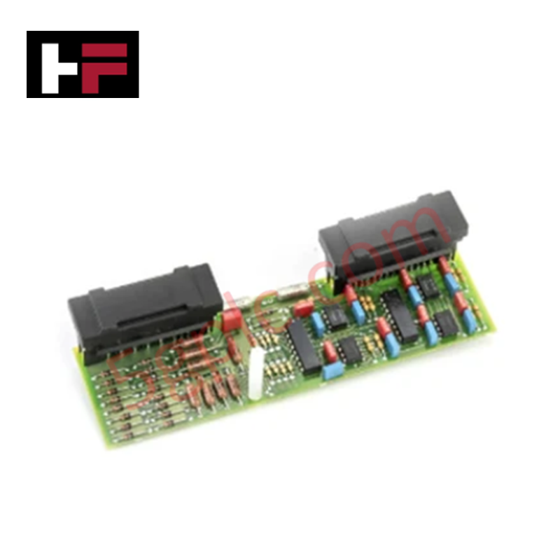
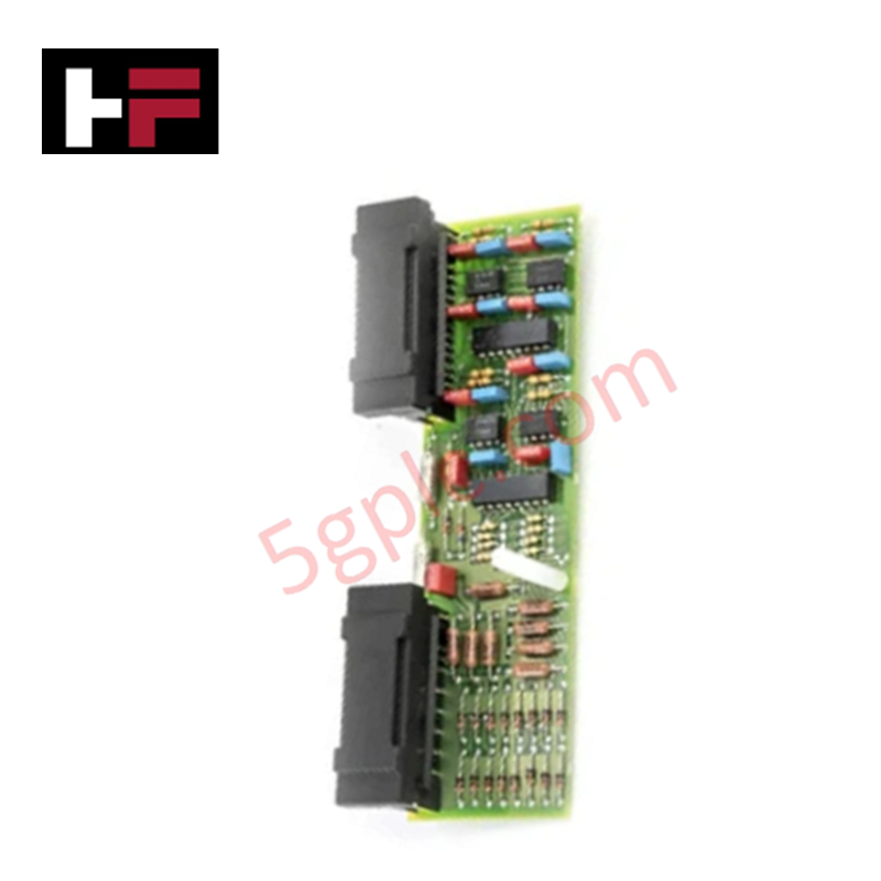
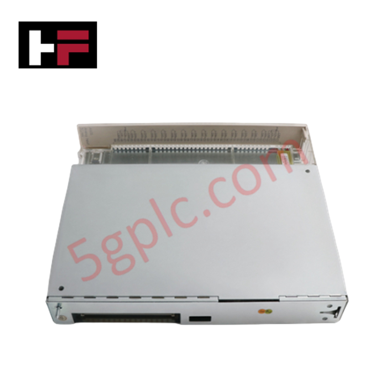
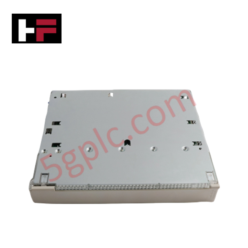
Configuré pour l’acquisition distribuée de signaux analogiques dans les architectures de contrôle de turbine LinkNet, le Woodward 9905-970 (Module d’entrée LinkNet 9905-970) assure l’exécution physique/électrique directe de la conversion des signaux des capteurs.
Spécifications matérielles
| Paramètre | Spécification |
|---|---|
| Modèle | 9905-970 |
| Marque | Woodward |
| Dimensions | 14 x 11 x 4 pouces |
| Température de fonctionnement | -40 à 85 °C |
| Consommation électrique | Entrée 24 VCC |
| Impédance du signal | 33 kOhms |
| Protection contre les transitoires | 900 VCC |
Réponse de la boucle de rétroaction de l’actionneur
Le module 9905-970 fonctionne comme un nœud distant au sein du réseau d’E/S distribuées LinkNet, convertissant les entrées des capteurs de terrain en paquets de données pour le contrôleur hôte. L’impédance d’entrée de 33 kOhms du module est conçue pour minimiser les effets de charge sur les instruments de processus sensibles. Le circuit interne comprend une protection contre les transitoires jusqu’à 900 VCC pour protéger le module contre les surtensions électriques courantes. Pour maintenir une performance stable de la boucle de rétroaction de l’actionneur, le câblage de terrain doit être acheminé de manière à éviter les interférences électromagnétiques à haute énergie, et l’adresse du module doit être correctement synchronisée avec les réglages du groupe de fréquence du réseau dans le contrôleur maître.
Questions fréquemment posées
Q : Quelle est la fonction principale de l’affichage LED de 24 caractères sur ce module ?
R : L’affichage LED intégré fournit une indication locale de l’état du module, incluant l’activité des canaux et le signalement des erreurs, ce qui facilite le diagnostic lors de la mise en service sur le terrain.
Q : Ce module peut-il fonctionner en continu à la température maximale spécifiée de 85 °C ?
R : Le module est conçu pour fonctionner jusqu’à 85 °C. Cependant, assurez-vous que l’emplacement de montage dans l’armoire de contrôle offre une convection naturelle ou forcée suffisante pour éviter une accumulation locale de chaleur qui pourrait dépasser la température de fonctionnement nominale à la surface du module.
Consignes d’installation sur site
- Montage : Fixez le module à l’intérieur de l’armoire à l’aide des trous de fixation fournis. Veillez à ce que l’encombrement de 14 x 11 x 4 pouces permette un dégagement approprié pour le câblage de communication et de signal.
- Câblage : Utilisez un câble blindé à paires torsadées pour la connexion au bus LinkNet. Connectez les fils de signal aux borniers en respectant les polarités conformément au schéma de câblage du système.
- Blindage et mise à la terre : Raccordez les blindages des câbles à la borne de terre désignée sur le panneau de contrôle afin de réduire les bruits induits et garantir l’intégrité des données sur le réseau distribué.
- Configuration : Réglez les commutateurs d’adressage interne du nœud pour correspondre à la configuration programmée dans le logiciel du contrôleur hôte avant d’alimenter le module.
- Validation : Après l’installation, vérifiez l’état de l’affichage LED pour confirmer que le module a établi avec succès la communication avec le bus réseau.
Informations supplémentaires
- Pièces 100 % d'origine : Tous les produits sont originaux et authentiques, garantissant des performances industrielles fiables.
- Garantie de remboursement de 30 jours : Retournez tout article en stock dans les 30 jours dans son emballage d'origine non ouvert pour un remboursement complet (hors frais de port et frais).
- Garantie de 12 mois : Couvre les défauts de matériaux ou de fabrication ; exclut les mauvais usages, l'usure normale ou les modifications non autorisées.
- Expédition mondiale : Nous expédions via USPS, UPS, FedEx et DHL. Les délais de livraison varient selon le pays et peuvent être soumis à des frais de douane ou d'importation.
- Assistance & Contact : Une assistance technique et garantie est disponible à tout moment. Contactez-nous ici : Contact.
- Conseils d'achat : Vérifiez attentivement les spécifications et la compatibilité du produit avant de commander pour assurer une application correcte.
Guide technique et d'achat

Comprendre les contacts secs dans le câblage PLC : un guide d'automatisation industrielle
Maîtriser les principes de commutation des contacts est essentiel pour des panneaux de contrôle fiables. Les dispositifs de terrain et les automates programmables (PLC) communiquent via des contacts secs ou humides. Ce guide technique examine le fonctionnement des contacts secs, explore leurs architectures de câblage et évalue leurs principaux avantages dans l'automatisation industrielle.

Liste de contrôle ultime pour la mise en service des systèmes d'automatisation industrielle : un guide d'ingénierie
La mise en service est la phase la plus décisive d’un projet d’automatisation industrielle, transformant le matériel et le logiciel de contrôle en une installation opérationnelle. Des tests rigoureux évitent des retards coûteux au démarrage et renforcent la confiance du client. Ce guide couvre les listes de contrôle essentielles, les normes électriques et les meilleures pratiques.

Systèmes d'automatisation redondants : architecture de base, valeur commerciale et avantages techniques
Les arrêts imprévus représentent une menace financière majeure pour la fabrication de procédés. Pour éviter des interruptions coûteuses, les ingénieurs déploient des architectures redondantes de PLC et DCS qui garantissent un fonctionnement continu en cas de défaillance matérielle. Ce guide technique explore les principes de redondance, les nœuds critiques du système et des scénarios réels.