


Produktdetails
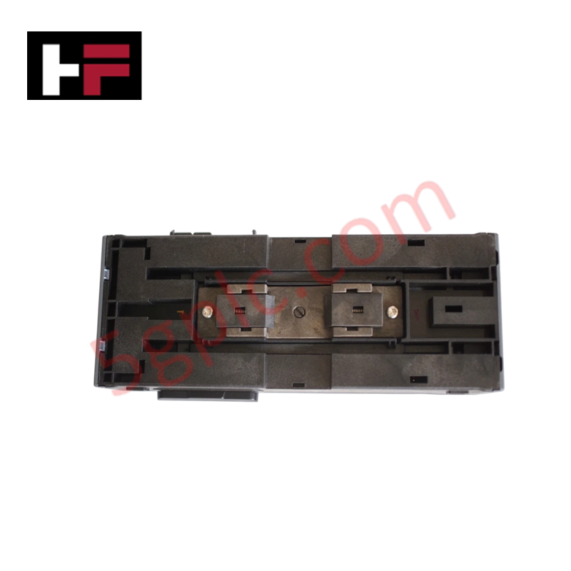
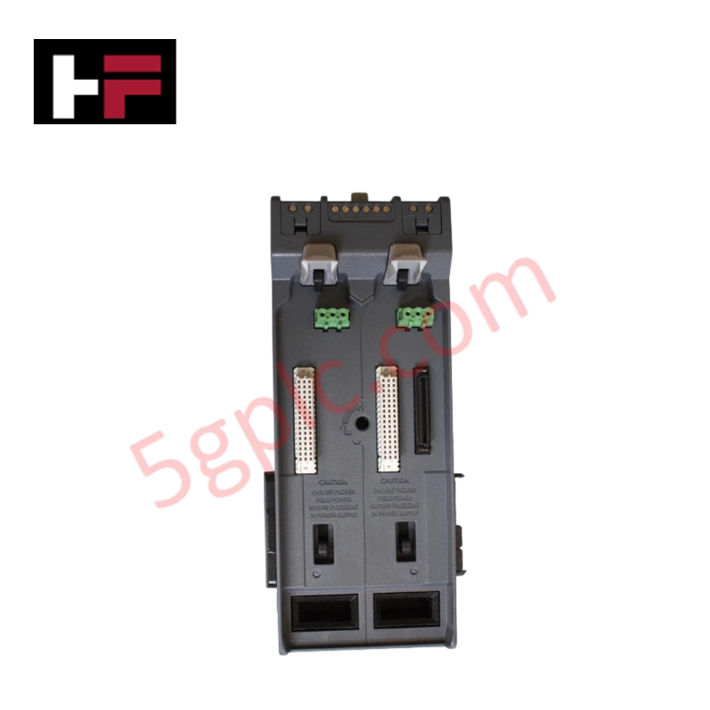
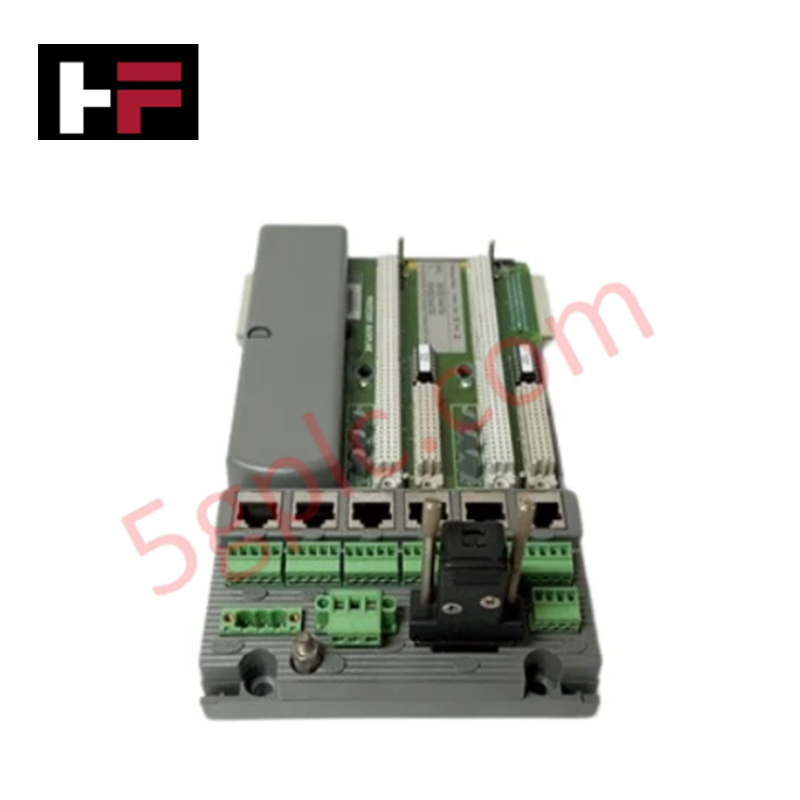
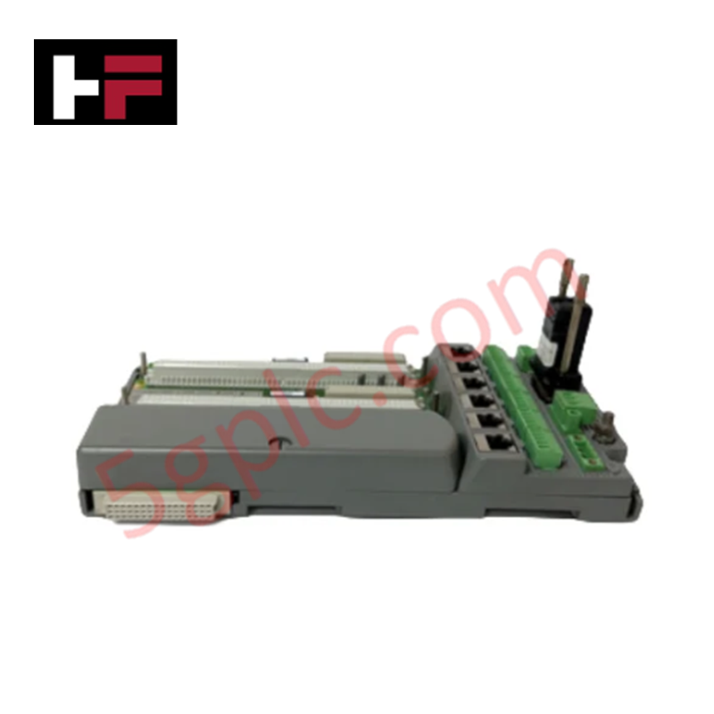
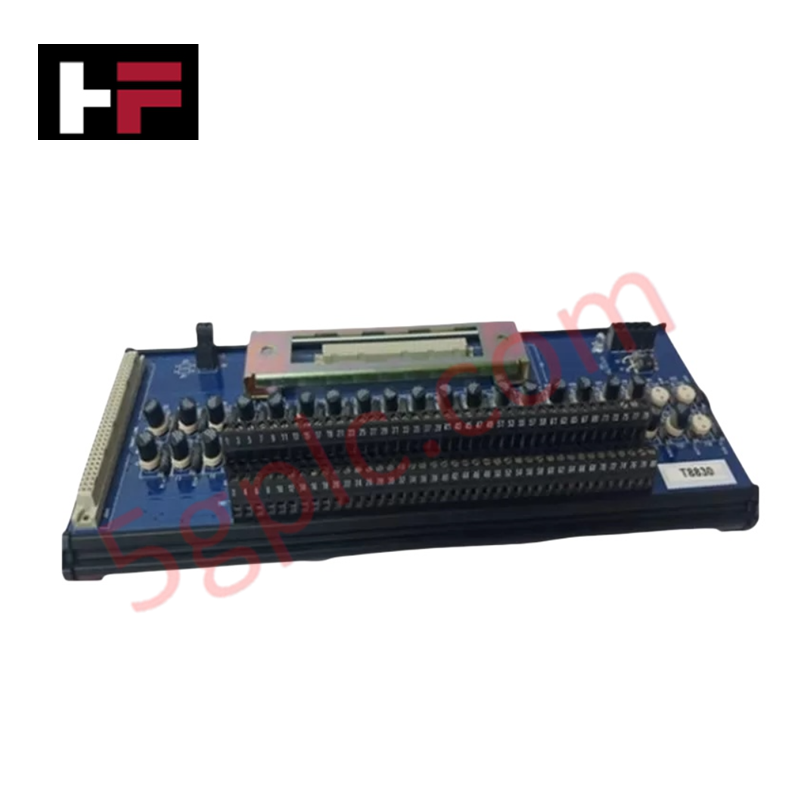
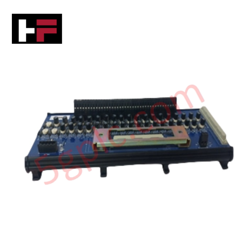
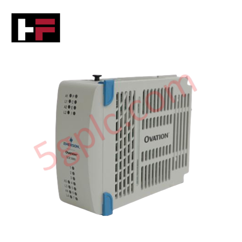
Configured for power distribution and management in DeltaV control networks, the Emerson KJ4005X1-BA1 (KJ4005X1-BA1 2-Wide Power Controller Carrier) provides direct physical/electrical execution of bus power regulation and field power distribution.
Hardware Specifications
| Parameter | Specification |
| Model | KJ4005X1-BA1 |
| Brand | Emerson |
| Origin | USA |
| Weight | 0.5 kg (1.0 lb) |
| Dimensions | 10.2 cm x 22.9 cm x 6.3 cm |
| Operating Temp | -40 deg C to +70 deg C |
| Power Consumption | 12 VDC Local Bus / 30 VDC Field Power |
| Local Bus Power | 12 VDC at 15 A |
| Field Power | 30 VDC at 3 A per card |
Process Control: Channel-to-Channel Isolation
The KJ4005X1-BA1 carrier is engineered to maintain electrical separation between the local bus power and field power distribution paths. This architecture utilizes integrated galvanic isolation to prevent noise transmission from field-side actuator loops back to the primary controller bus. By maintaining strict dielectric boundaries and utilizing a low-impedance ground plane, the carrier ensures that transients or localized shorts in field circuits do not compromise the stability of the 12 VDC local bus. The design specifically supports high-density configurations, ensuring that isolation remains effective even under maximum load conditions of 15 A on the local bus and 3 A per card on the field power rails.
Frequently Asked Questions (FAQ)
Q: Can this carrier be used in high-corrosion environments?
A: Yes. The KJ4005X1-BA1 is certified to meet ISA-S71.04-1985 Class G3 standards for airborne contaminants, allowing for reliable operation in environments where corrosive gases are present, provided that standard enclosure sealing requirements are met.
Q: Is this carrier susceptible to performance degradation from mechanical vibration?
A: The carrier is rated for vibration resistance up to 1 mm peak-to-peak (2-13.2 Hz) and 0.7 g (13.2-150 Hz). Ensure that all module locking mechanisms are fully engaged and that the carrier is mounted on a rigid cabinet backplane to comply with these mechanical specifications.
Field Installation Guidelines
-
Mounting: Secure the carrier to the mounting surface using the provided fastener points. Ensure the carrier is oriented vertically to optimize natural convection and heat dissipation for the 12 VDC and 30 VDC power circuitry.
-
Grounding: Terminate the carrier chassis to the cabinet earth ground bus. A low-impedance grounding connection is mandatory to maintain the integrity of the integrated shield planes and protection against transient voltage spikes.
-
Wiring: Utilize properly sized conductors for the 30 VDC field power input to minimize voltage drop. All field power wiring must be segregated from low-level analog signal cabling to prevent inductive coupling.
-
Load Balancing: Verify that current draw from connected I/O cards does not exceed the 3 A limit per card on the field power rails. Monitor local bus loading to ensure total current remains within the 15 A rating.
Zusätzliche Informationen
- 100% Originalteile: Alle Produkte sind original und authentisch, was eine zuverlässige industrielle Leistung gewährleistet.
- 30-Tage Rückgabegarantie: Rückgabe aller vorrätigen Artikel innerhalb von 30 Tagen in der originalen, ungeöffneten Verpackung für eine volle Rückerstattung (ohne Versandkosten und Gebühren).
- 12 Monate Garantie: Deckt Material- oder Verarbeitungsfehler ab; schließt Missbrauch, normalen Verschleiß oder unautorisierte Änderungen aus.
- Weltweiter Versand: Wir versenden über USPS, UPS, FedEx und DHL. Die Lieferzeiten variieren je nach Land und können Zoll- oder Einfuhrgebühren unterliegen.
- Support & Kontakt: Technische und Garantieunterstützung ist jederzeit verfügbar. Kontaktieren Sie uns hier: Kontakt.
- Kaufberatung: Überprüfen Sie vor der Bestellung sorgfältig die Produktspezifikationen und Kompatibilität, um eine korrekte Anwendung sicherzustellen.


Technik- & Kaufberatung
PLC vs. PAC: Auswahl in der modernen Industrieautomation meistern
Die Auswahl des richtigen Controllers ist eine grundlegende Entscheidung in der industriellen Automatisierung. Obwohl die Grenzen zwischen speicherprogrammierbaren Steuerungen (SPS) und programmierbaren Automatisierungscontrollern (PAC) oft verschwimmen, ist das Verständnis ihrer grundlegenden architektonischen Unterschiede für die Zuverlässigkeit des Systems entscheidend. Beide Controller fungieren als das Gehirn von Steuerungssystemen, doch ihre spezifischen Fähigkeiten bestimmen ihre Eignung für verschiedene Aufgaben der Fabrikautomatisierung.
Die Transformation der Textilherstellung: Die strategische Integration von Industrieautomation und KI
Die Textilindustrie steht an einem entscheidenden technologischen Wendepunkt. Traditionelle Betriebe müssen nun die digitale Transformation annehmen, um auf dem globalen Markt wettbewerbsfähig zu bleiben. Durch die Integration fortschrittlicher industrieller Automatisierung – von PLC-gesteuerten Maschinen bis hin zu ausgefeilten KI-gestützten Analysen – können Hersteller die Produktivität erheblich steigern, Materialverschwendung minimieren und die Gesamtqualität der Produkte verbessern.
Navigation durch industrielle Kommunikationsprotokolle: Ein technischer Leitfaden für moderne SPS-Systeme
Im Bereich der Industrieautomation dient die speicherprogrammierbare Steuerung (SPS) als das Gehirn der Fabrikhalle. Ihre wahre Stärke entfaltet sie jedoch durch robuste Kommunikationsprotokolle. Diese digitalen Verbindungen gewährleisten einen nahtlosen Datenaustausch zwischen Steuerungen, Sensoren und Managementsystemen auf Unternehmensebene.