










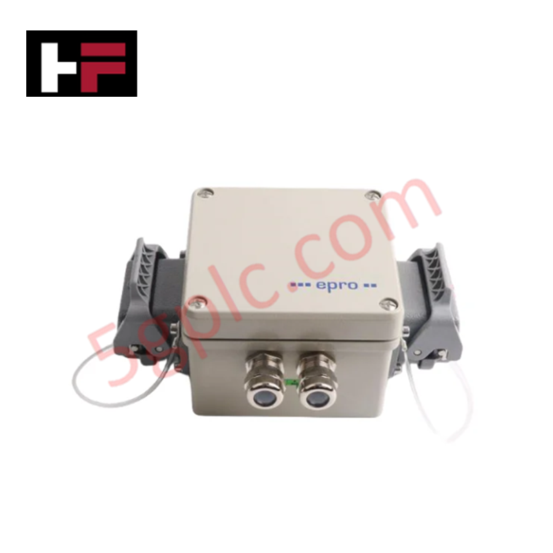
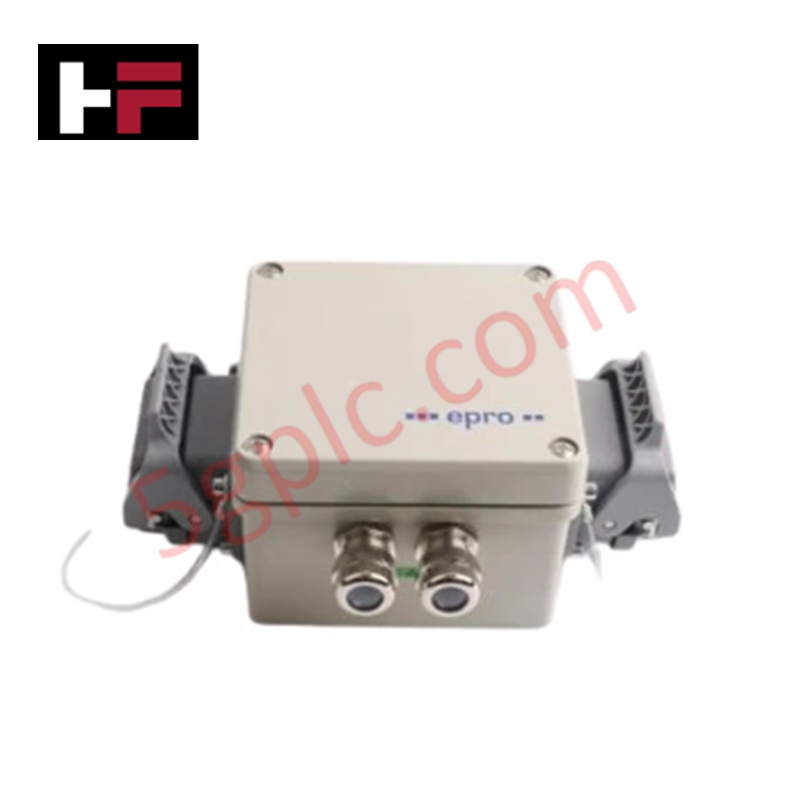


Product Details
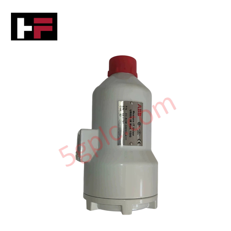
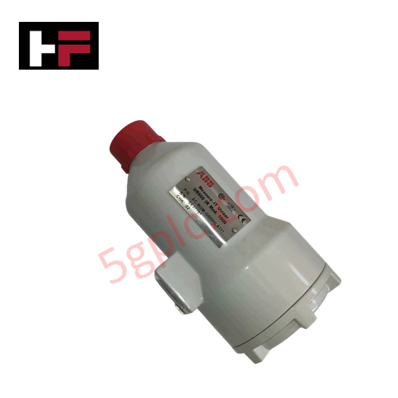
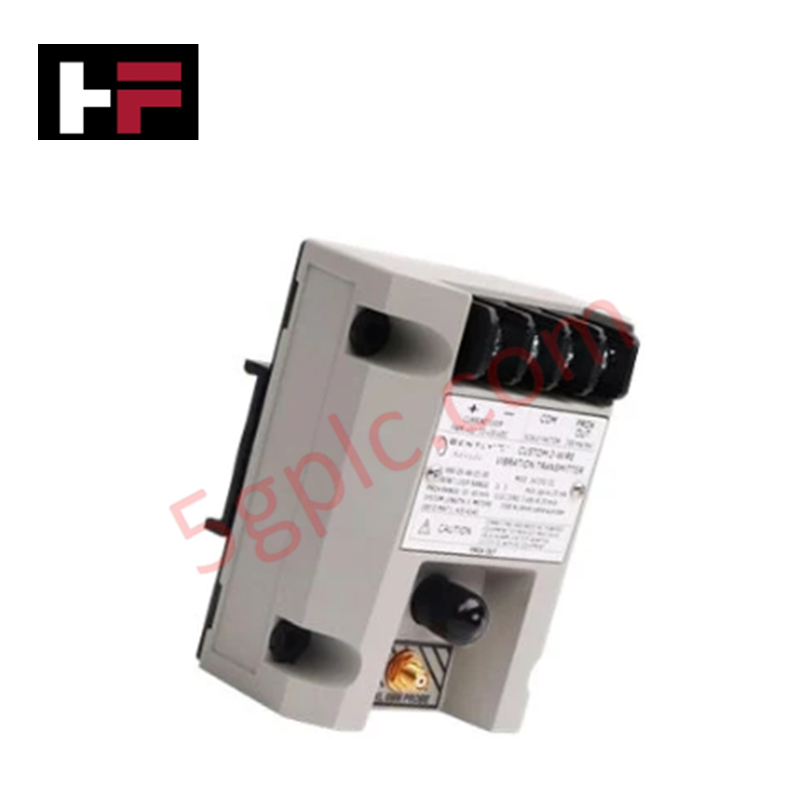
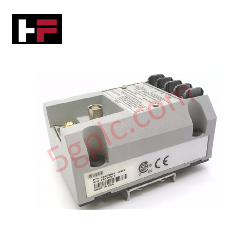
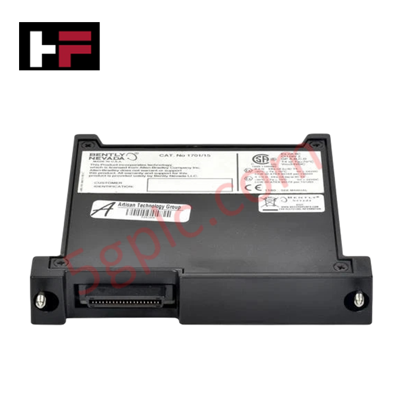
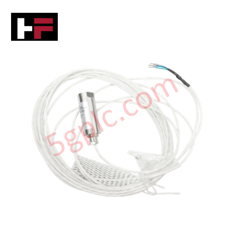
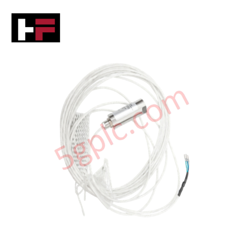
Configured for seismic vibration acquisition in machinery monitoring platforms, the Emerson EPRO MMS 3120/022-000 (MMS3120/022-000) Dual Channel Bearing Vibration Transmitter provides direct electrical execution of dual-channel signal conditioning and output transmission.
Hardware Specifications
| Parameter | Specification |
|---|---|
| Model | MMS 3120/022-000 |
| Brand | Emerson EPRO |
| Weight | 1.3 kg |
| Dimensions | 127.5 mm x 125.75 mm x 80 mm |
| Operating Temp | Standard industrial range |
| Power Consumption | Dual redundant 24 VDC inputs |
| Measurement Inputs | 2 independent channels (electrodynamic/piezoelectric) |
| Output | Configurable 0/4-20 mA |
Process Control and DCS Connectivity
The MMS 3120/022-000 facilitates integration with DCS environments via configurable 0/4-20 mA current outputs. Each channel provides independent signal processing, ensuring channel-to-channel isolation that prevents ground loops between sensor inputs and the process control loop. The transmitter architecture utilizes internal diagnostics to monitor for sensor faults or circuit-level failures, reporting status through relay outputs to maintain loop availability and fault-tolerant operation.
Frequently Asked Questions
Q: How does the dual redundant 24 VDC power input affect installation?
A: The transmitter accepts two independent 24 VDC power sources. The internal circuitry is designed to draw power from either source, ensuring that the measurement loop remains energized and operational even if one supply line experiences a failure or disconnects.
Q: Can this unit detect sensor-level open circuits?
A: Yes. The system incorporates continuous sensor monitoring and signal integrity checks. If the transducer input enters an open-circuit or short-circuit state, the module will trigger the fault relay output to indicate a loss of data validity.
Field Installation Guidelines
- Secure the transmitter to a vibration-damped mounting surface to avoid base-plate resonance interference with the seismic sensor inputs.
- Terminate the sensor shielding at the dedicated earth ground point to maintain galvanic isolation and reduce electromagnetic noise coupling into the velocity or acceleration signal path.
- Verify that the current loop load resistance is within the transmitter capability before energizing the 4-20 mA output.
- Route signal cabling through grounded conduits and ensure physical separation from high-power AC motor drives.
- Perform a static signal simulation test during commissioning to verify the mapping of the measured vibration parameters to the output current values.
Additional Information
- 100% Genuine Parts: All products are original and authentic, ensuring reliable industrial performance.
- 30-Day Refund Guarantee: Return any in-stock item within 30 days in original, unopened packaging for a full refund (excluding shipping and fees).
- 12-Month Warranty: Covers defects in materials or workmanship; excludes misuse, normal wear, or unauthorized modifications.
- Worldwide Shipping: We ship via USPS, UPS, FedEx, and DHL. Delivery times vary by country and may be subject to customs or import fees.
- Support & Contact: Technical and warranty assistance is available anytime. Contact us here: Contact.
- Purchase Guidance: Check product specifications and compatibility carefully before ordering to ensure proper application.

Tech & Buying Guide

Redundant Automation Systems: Maximizing Uptime in Critical Control Applications
Industrial automation relies on continuous operational stability to prevent catastrophic downtime and financial loss. While standard dictionary definitions treat redundancy as superfluous, industrial engineers consider redundant control architectures indispensable for high-availability systems. Implementing backup hardware ensures seamless takeover during primary equipment failures, protecting critical infrastructure across manufacturing and process industries.
Demystifying the 5 Levels of Industrial Automation Architecture
Modern manufacturing relies on structured communication hierarchy to bridge physical shop-floor hardware with enterprise management software. This framework, commonly known as the Automation Pyramid, establishes how data flows between field devices, logic controllers, and corporate IT networks. Understanding these five distinct levels helps engineers and plant managers optimize system operations, reduce downtime, and implement seamless factory automation solutions.

Transforming Shop Floor Data into Actionable Insights: A Deep Dive into MES
Manufacturing Execution Systems serve as the digital backbone of modern factory floors. Positioned at Level 3 of the ISA-95 automation pyramid, MES links enterprise resource planning with real-time shop floor control systems. Today, industrial operators rely on MES software to bridge operational strategy with physical production execution.