


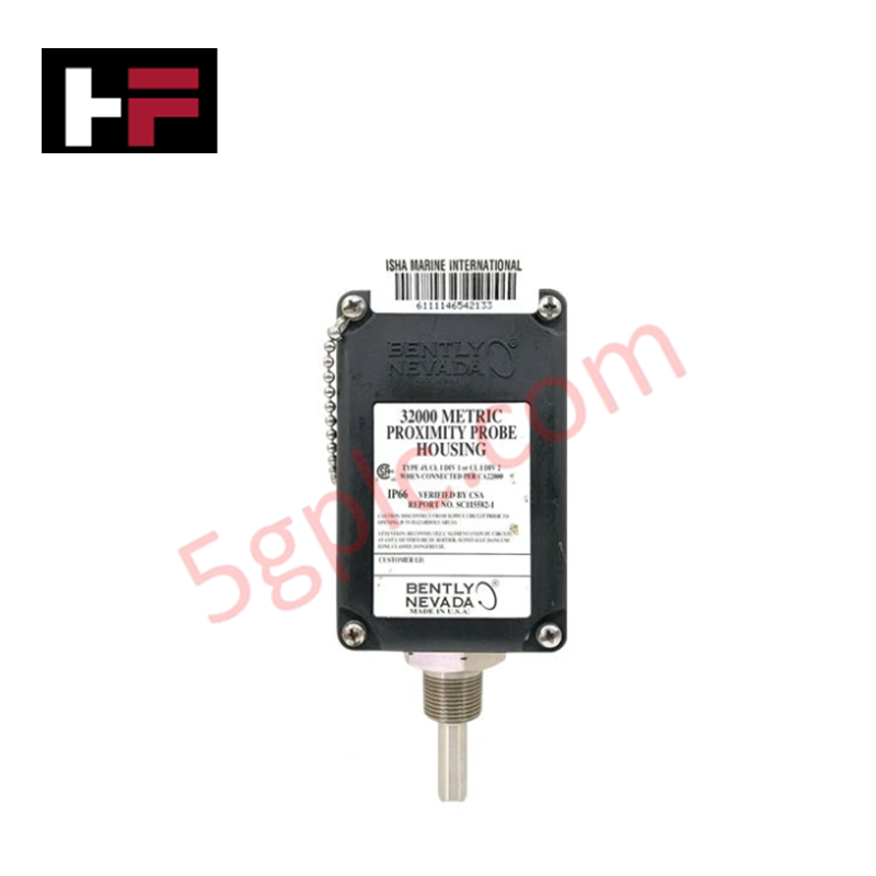
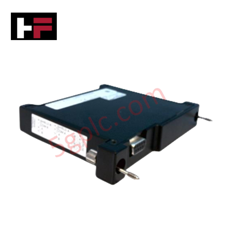
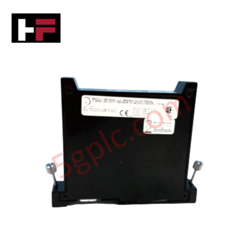
Product Details
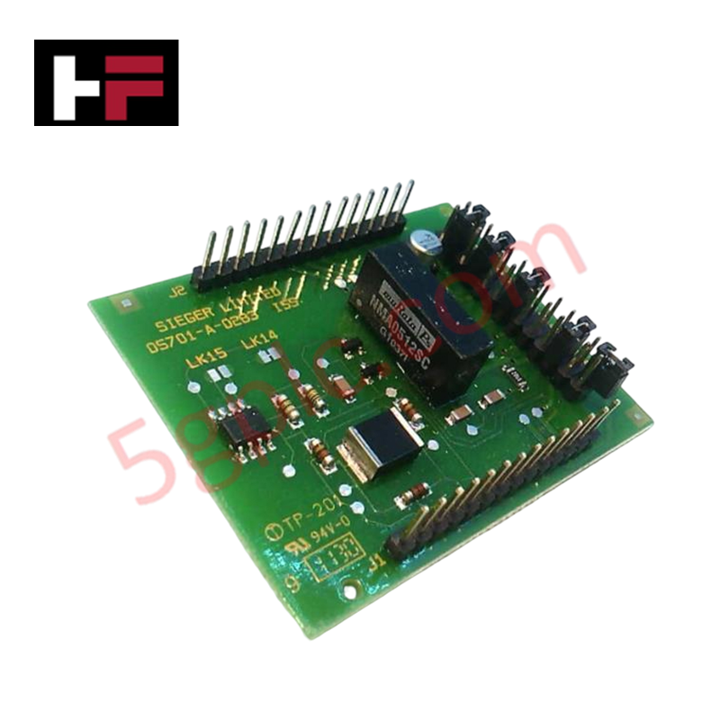
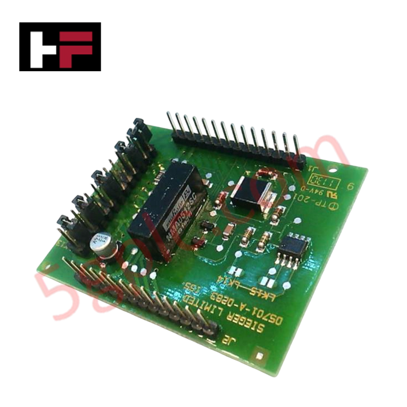
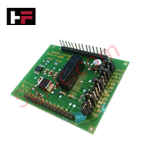
The Honeywell 05701-A-0283, also cataloged as the 05701-A-0283 Sensor Drive Module, operates as a dedicated hardware component for signal conditioning and sensor excitation within System 57 gas detection controller platforms. This module provides direct electrical interface management to sustain precise excitation currents for connected gas sensing elements and processes return signals for controller input.
Hardware Specifications
| Parameter | Specification |
|---|---|
| Model | 05701-A-0283 |
| Brand | Honeywell |
| Origin | USA |
| Weight | 0.023 kg |
| Dimensions | Standard System 57 card format |
| Operating Temp | Consult System 57 environmental specifications |
| Power Consumption | Dependent on connected sensor load |
| Function | Sensor excitation and signal drive |
Channel-to-Channel Isolation
The 05701-A-0283 module utilizes internal galvanic isolation to ensure signal integrity across the sensing interface. This architectural design prevents cross-channel interference and protects the sensor drive circuitry from common-mode voltage fluctuations that may occur within the System 57 rack environment. Maintaining electrical isolation between the sensor excitation path and the main controller backplane is necessary to minimize signal noise and ensure the accuracy of gas concentration readings during varying operational conditions.
Frequently Asked Questions
Q: Can the 05701-A-0283 be hot-swapped while the System 57 controller is powered?
A: No. Any attempt to insert or remove the sensor drive module under power may cause electrical transients or backplane connector damage. De-energize the rack before performing any module maintenance.
Q: How should the sensor lead-wire impedance be managed?
A: Ensure that the resistance of the cabling between the sensor and this module does not exceed the manufacturer-specified limits to prevent voltage drops that could affect the excitation voltage stability at the sensor head.
Field Installation Guidelines
- Physical Mounting: Carefully insert the module into the designated System 57 chassis slot. Verify proper alignment with the backplane connector to avoid terminal pin deformation or improper signal contact.
- Shielding and Grounding: Utilize high-quality shielded twisted-pair cabling for all sensor connections. Terminate the shield at the cabinet ground point to suppress electromagnetic interference and prevent ground loops.
- Cable Routing: Isolate sensor signal wiring from high-voltage AC power cables and motor control leads. A minimum separation distance of 150 mm is recommended to preserve signal fidelity.
- Connection Verification: After physical installation, verify continuity and ensure all terminal connections are secure to prevent intermittent signal loss or fluctuations in the gas detection loop.
Additional Information
- 100% Genuine Parts: All products are original and authentic, ensuring reliable industrial performance.
- 30-Day Refund Guarantee: Return any in-stock item within 30 days in original, unopened packaging for a full refund (excluding shipping and fees).
- 12-Month Warranty: Covers defects in materials or workmanship; excludes misuse, normal wear, or unauthorized modifications.
- Worldwide Shipping: We ship via USPS, UPS, FedEx, and DHL. Delivery times vary by country and may be subject to customs or import fees.
- Support & Contact: Technical and warranty assistance is available anytime. Contact us here: Contact.
- Purchase Guidance: Check product specifications and compatibility carefully before ordering to ensure proper application.


Tech & Buying Guide

Redundant Automation Systems: Ensuring Continuous Uptime in Critical Control Infrastructure
System reliability directly determines operational profitability across high stakes process industries. Modern industrial automation platforms must eliminate single points of failure to prevent catastrophic shutdowns. Deploying fault tolerant architecture safeguards complex facilities against unexpected hardware glitches, network disruptions, and maintenance outages.

Understanding Types of Noise in Electronic Circuits and Control Systems
Signal integrity directly determines measurement accuracy and loop stability across industrial automation environments. Electronic noise introduces unwanted stochastic interference into analog loops, sensor feedback lines, and digital fieldbus networks. Understanding how intrinsic electronic noise and external electromagnetic interference manifest allows control engineers to optimize signal conditioning and shield sensitive instrumentation effectively.

Why 24V DC Power Supplies Standardize Modern Industrial Automation
Industrial control cabinets worldwide rely on 24V DC as the universal power standard for field instrumentation, sensors, and controllers. Walk into any manufacturing plant, and you will find PLCs, human-machine interfaces (HMIs), and smart actuators running on extra-low voltage DC. Standardizing on 24V DC enhances operational safety, lowers cabinet footprint, and maintains steady control performance across factory networks.