










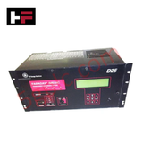
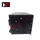
Product Details
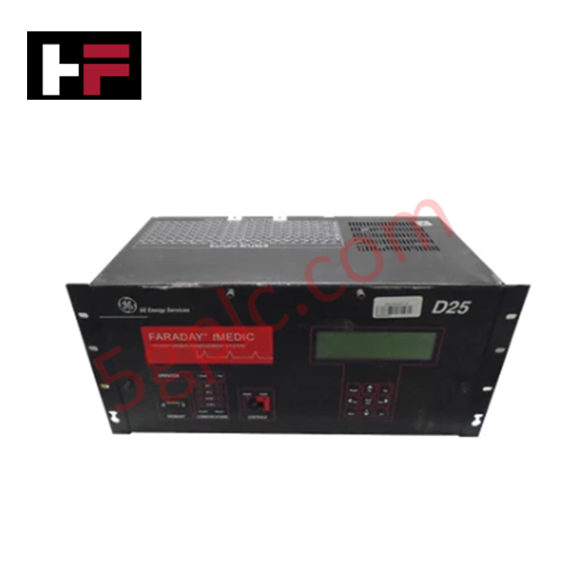
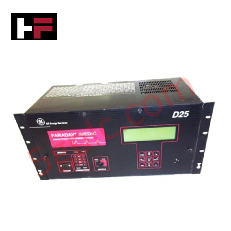
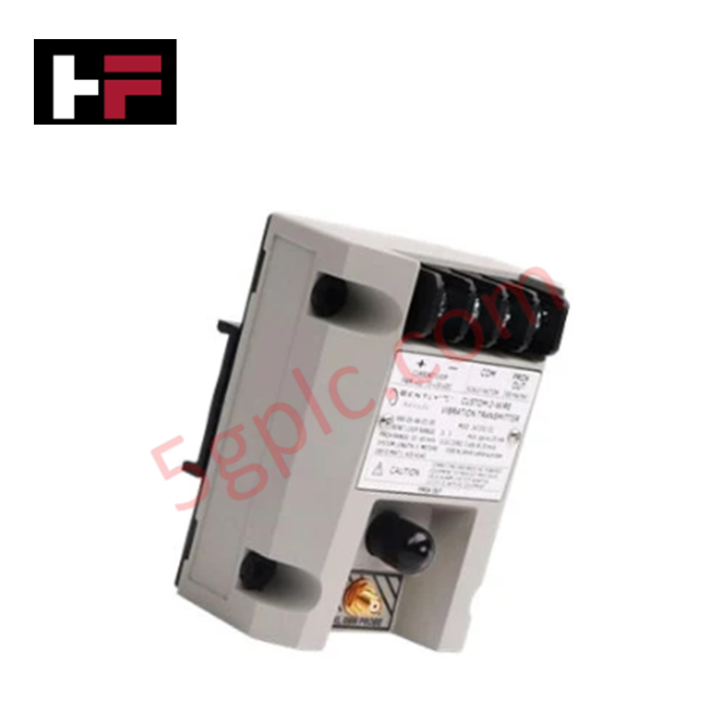
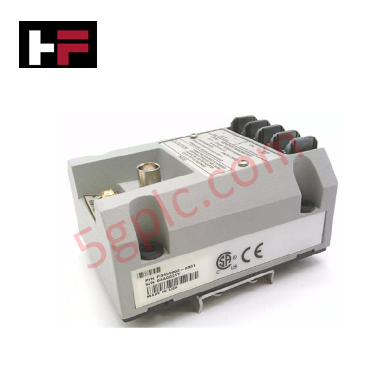
The GE Fanuc D25-0157-000003, also cataloged as the D25 Measurement and Control Device, operates as a dedicated hardware component for specific technical task execution within industrial automation and network platforms. The component ingests high-accuracy electrical telemetry across integrated AC current, DC current, and DC voltage physical interface nodes. By calculating waveforms from multi-range CT links and instrument loops, the module services localized digital fault recording (DFR) and real-time regulation routines over active internal processing buses.
Hardware Specifications
| Parameter | Specification |
|---|---|
| Model | D25-0157-000003 |
| Brand | GE Fanuc |
| Origin | Technical specifications determine factory origin |
| Weight | Internal hardware option selection dependent |
| Dimensions | Standard D25 series chassis envelope requirements apply |
| Operating Temp | Industrial grade environmental classification |
| Power Consumption | Base processor draw plus active measuring channel configuration loads |
| Nominal CT Input Options | 1 A rms or 5 A rms |
| AC Measurement Range | 2% to 1600% of nominal; 2% to 4200% (asymmetrical) for DFR/protection |
| Thermal Overload Limits | 4x nominal continuous; 30x nominal for 10 seconds; 100x nominal for 1 second; 10-minute duty cycle for parameters exceeding 4x nominal |
| AC Accuracy Metrics | Accuracy: +/-0.5% to +/-0.3% of nominal; Frequency: +/-0.03 Hz; Phase Angle: +/-0.5 deg |
| DC Current Ranges | +/-1 mA, +/-5 mA, +/-10 mA, +/-20 mA nominal |
| DC Current Accuracy | +/-0.10% of full scale |
| DC Voltage Input Span | Nominal: +/-5 Vdc; Measurement range: +/-6 Vdc |
| DC Voltage Accuracy | +/-0.05% of full scale |
Profinet / EtherNet/IP Deterministic Networks Integration
The module manages input scaling through its internal analog-to-digital matrix, utilizing fixed software filtering blocks to maintain firmware flash compatibility across concurrent operating cycles. High-density I/O registers serialize the +/-20 mA DC current loops and +/-6 Vdc voltage inputs into the memory map, isolating transient electrical noise from the primary processor backplane communication channel. This architectural separation preserves deterministic communication performance, preventing host communication packet peaks from delaying the 1 ms fault-recording triggers managed by the AC protection circuits.
Frequently Asked Questions
Q: How is the 4200% asymmetrical AC current measurement range managed by the DFR firmware without causing memory overflows?
A: The onboard analog-to-digital conversion matrix reserves dedicated high-headroom registers for transient surge inputs. When an asymmetrical fault step occurs, the internal scaling algorithms automatically track the over-range parameter without impacting firmware flash compatibility or disrupting concurrent DC loop sampling.
Q: Can the CT input terminals be disconnected while the primary power lines are under load?
A: No. Disconnecting active CT loops causes high-voltage open-circuit transients that can destroy the low-burden input resistors. The secondary current paths must be externally shorted or fully isolated before servicing any analog connector blocks on the D25-0157-000003.
Field Installation Guidelines
- Earthing and Grounding Frame: Bond the metal chassis ground screw directly to the main cabinet copper ground bus bar using a low-impedance grounding cable before routing any instrumentation lines.
- AC Input Shielding: Run all AC current transformer connections through dedicated twisted-shielded pairs, terminating the shield grounding braid strictly at the enclosure wall plate to block inductive interference.
- Low-Voltage Cable Trailing: Route the +/-5 Vdc voltage and low-current DC signal lines in distinct wiring ducts isolated from primary high-voltage AC switches and inductive control relay circuitry.
Additional Information
- 100% Genuine Parts: All products are original and authentic, ensuring reliable industrial performance.
- 30-Day Refund Guarantee: Return any in-stock item within 30 days in original, unopened packaging for a full refund (excluding shipping and fees).
- 12-Month Warranty: Covers defects in materials or workmanship; excludes misuse, normal wear, or unauthorized modifications.
- Worldwide Shipping: We ship via USPS, UPS, FedEx, and DHL. Delivery times vary by country and may be subject to customs or import fees.
- Support & Contact: Technical and warranty assistance is available anytime. Contact us here: Contact.
- Purchase Guidance: Check product specifications and compatibility carefully before ordering to ensure proper application.
Tech & Buying Guide

Transforming Shop Floor Data into Actionable Insights: A Deep Dive into MES
Manufacturing Execution Systems serve as the digital backbone of modern factory floors. Positioned at Level 3 of the ISA-95 automation pyramid, MES links enterprise resource planning with real-time shop floor control systems. Today, industrial operators rely on MES software to bridge operational strategy with physical production execution.

Managed Switch vs. Unmanaged Switch: Industrial Ethernet Architecture

Hot Standby vs. Cold Standby Redundancy in Industrial Automation
System availability determines process safety and productivity in industrial automation. Control engineers deploy redundancy to eliminate single points of failure. This technical guide evaluates Hot Standby vs. Cold Standby architectures, comparing failover speeds, memory sync, cost trade-offs, and field selection criteria.