










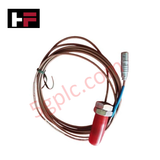
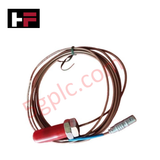
Product Details
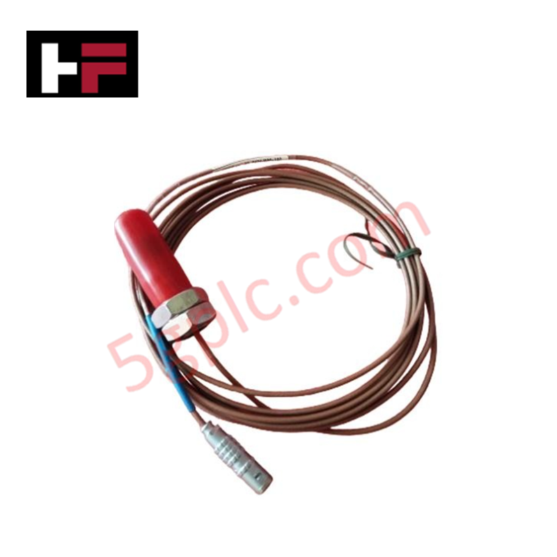
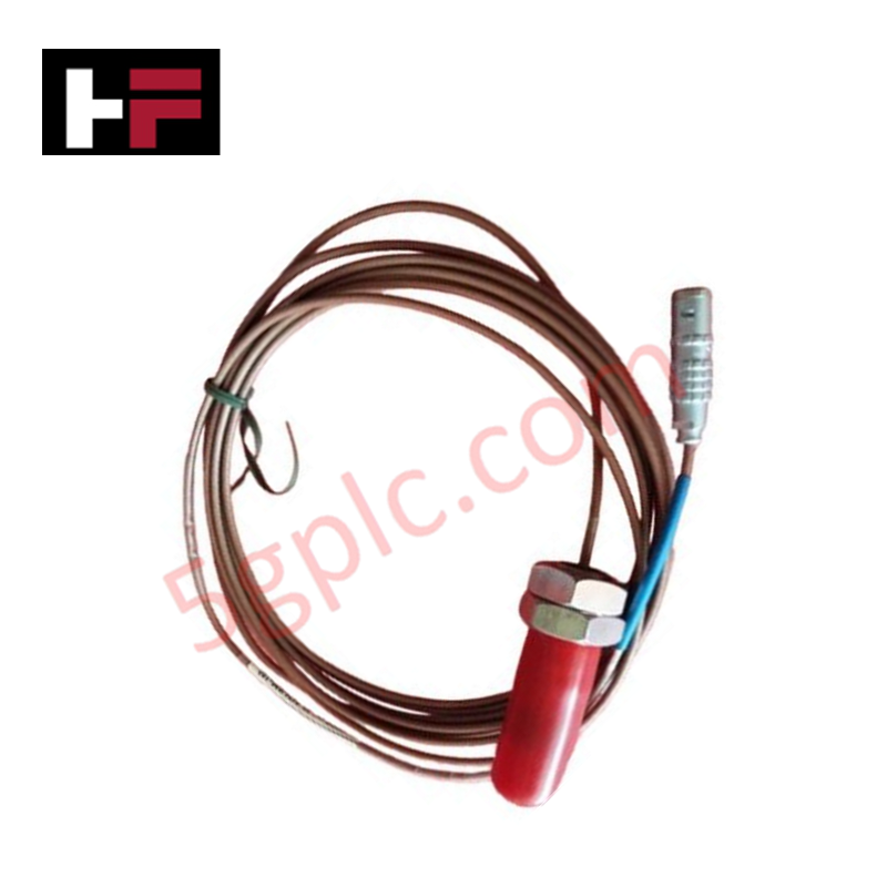
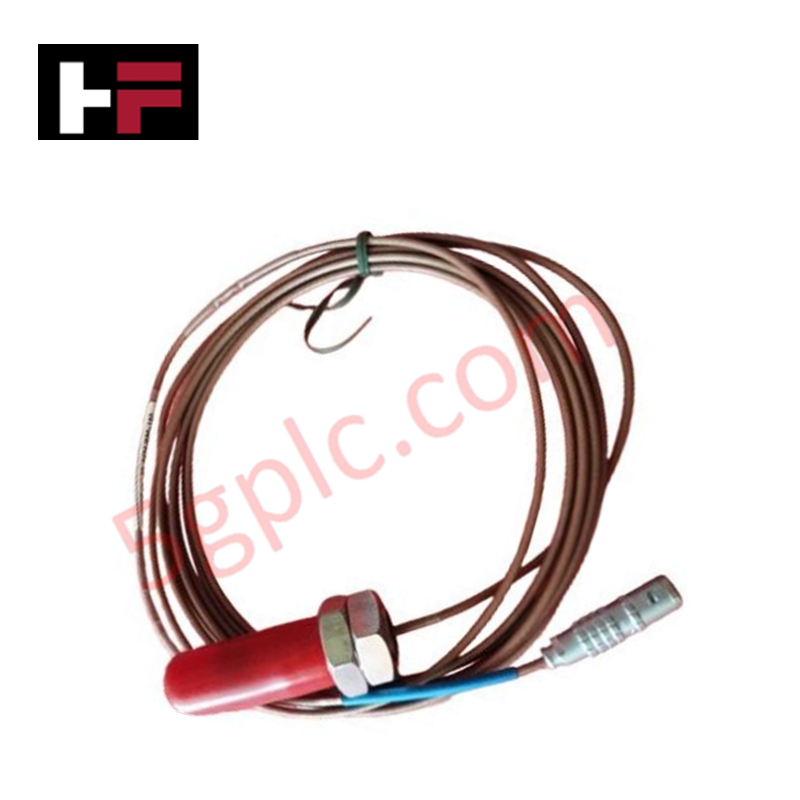
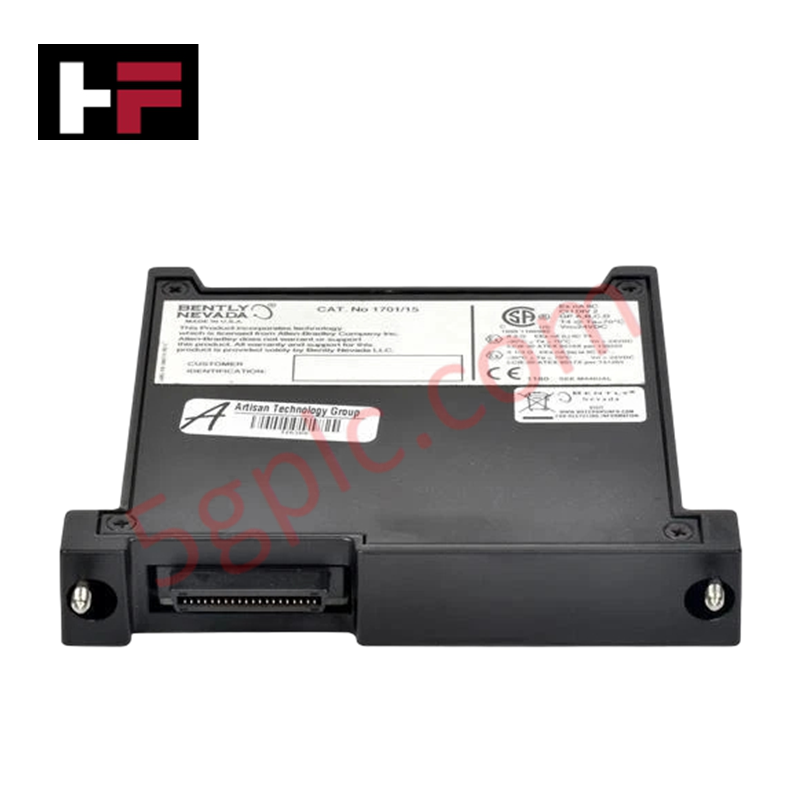
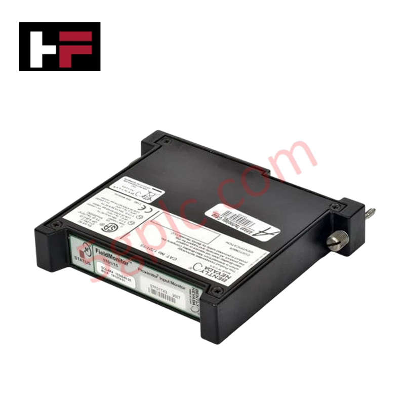
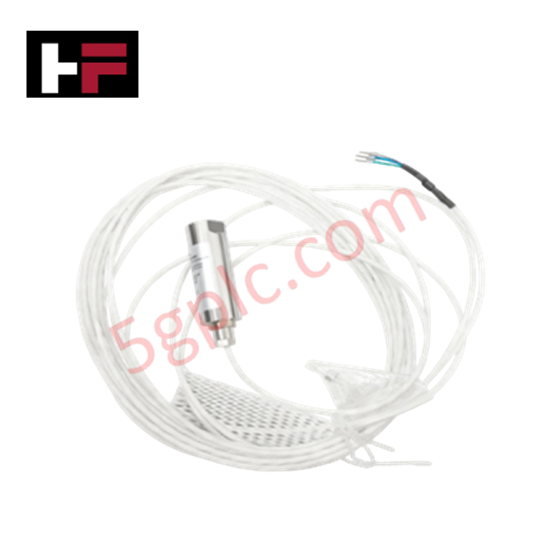
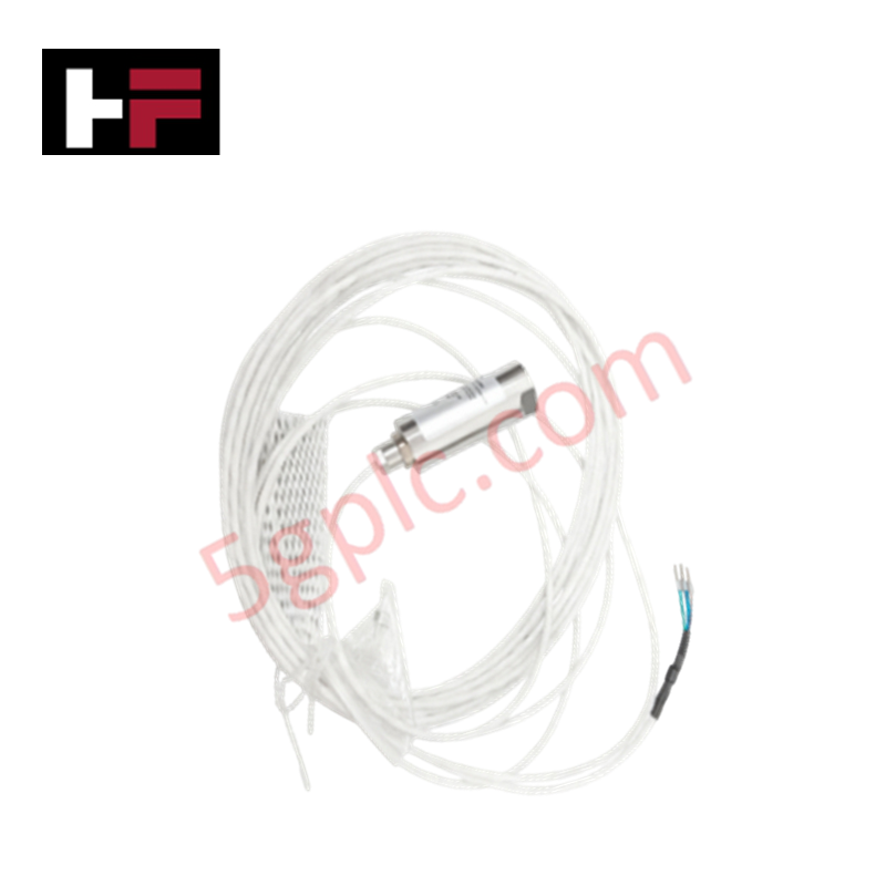
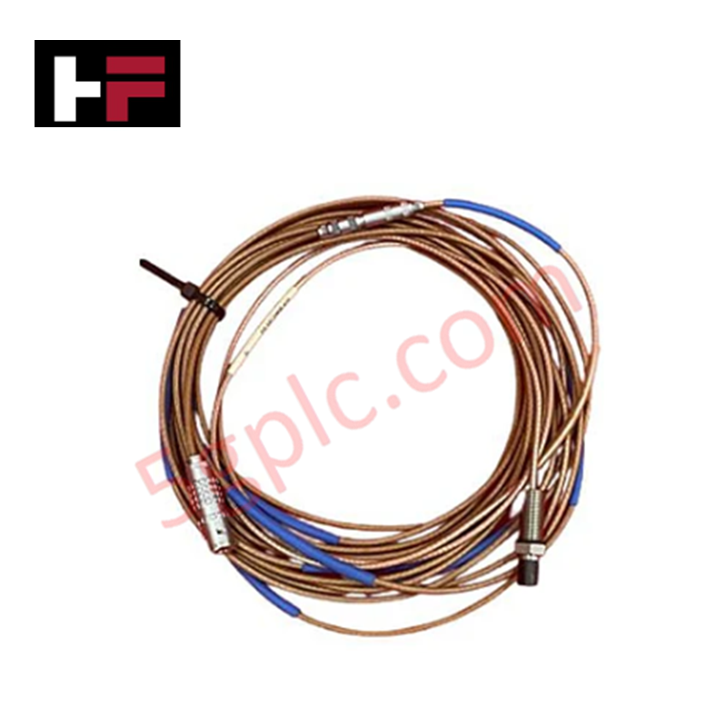
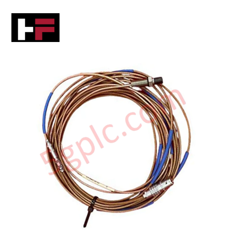
Configured for non-contact vibration and shaft displacement monitoring in rotating machinery, the Emerson PR6424/010-100 (PR6424 16 mm Eddy Current Sensor) provides direct physical/electrical execution. It measures radial dynamic motion and axial shaft position by generating dynamic high-frequency field damping when interfaced with Epro CON021 signal converters.
Hardware Specifications
| Parameter | Specification |
|---|---|
| Model | PR6424/010-100 |
| Brand | Emerson Epro |
| Origin | Germany |
| Weight | Approx. 0.20 kg |
| Dimensions | Probe Tip Diameter: 16 mm; Sleeve Thread: M18 x 1.5 |
| Operating Temp | -35 deg C to +150 deg C |
| Power Consumption | Driven via external converter (CON021 / EZ1000) |
| Measurement Range | Static: +-2.0 mm; Dynamic: 0 to 1000 um |
| Output Signal | Dynamic voltage via signal converter |
| Sensitivity | 4 V/mm (101.6 mV/mil) |
| Frequency Response | 0 Hz to 20 kHz (-3 dB) |
| Linearity | <= +-1.5% full scale |
| Cable Options | 5 m integral cable with stainless steel flexible armor and LEMO end |
| Probe Tip Material | High-temperature epoxy resin cap / PEEK |
| Protection Rating | IP67 (head / threaded body) |
| Target Material | Ferromagnetic steel (standard 42CrMo4) |
Eddy-Current Probe Scaling and Gap Voltage Validation
The Emerson PR6424/010-100 requires precise eddy-current probe scaling to convert high-frequency electromagnetic field damping into an accurate position signal across its nominal 4 mm linear measuring range. With a standardized sensitivity of 4 V/mm, proper installation relies on initial gap voltage validation (targeting approximately 2.7 mm mechanical center air gap or -10 VDC static offset via CON021 conditioning hardware) prior to securing the M18 lock nuts. Correct spatial positioning prevents cross-talk suppression degradation from nearby metal casing walls and limits measurement drift caused by shaft runout or structural rotor dynamics.
Frequently Asked Questions
Q: How is the physical air gap set during mechanical installation of the PR6424/010-100?
A: Thread the M18 x 1.5 sleeve into the mounting bracket until the DC gap voltage at the CON021 converter output reads the designated center value (-10 VDC nominal offset, corresponding to an approximate 2.7 mm air gap) before torquing lock nuts.
Q: Can the 5 m integral cable with LEMO connector be modified or spliced in the field?
A: Splicing or trimming the integral cable alters total system capacitance and inductance, which directly corrupts the calibrated 4 V/mm probe sensitivity and introduces non-linear measuring errors.
Q: What structural precautions prevent side-wall interference on the 16 mm probe tip?
A: Maintain a counterbore clearance area around the epoxy tip free of secondary metallic materials to avoid artificial damping of the RF magnetic field.
Field Installation Guidelines
- Thread the M18 x 1.5 stainless steel sleeve into tapped mounting points, ensuring a minimum engagement of 5 full threads before locking with jam nuts.
- Provide at least 30 mm of clear radial space around the 16 mm sensor head to eliminate unwanted eddy-current coupling with surrounding machine housings.
- Route the armored flexible cable through dedicated grounded metallic conduit, observing a minimum bend radius of 35 mm to prevent inner core damage.
- Connect the LEMO plug securely to the driver interface module, keeping the instrument shield grounded exclusively at the monitoring rack end to prevent ground loop noise.
Additional Information
- 100% Genuine Parts: All products are original and authentic, ensuring reliable industrial performance.
- 30-Day Refund Guarantee: Return any in-stock item within 30 days in original, unopened packaging for a full refund (excluding shipping and fees).
- 12-Month Warranty: Covers defects in materials or workmanship; excludes misuse, normal wear, or unauthorized modifications.
- Worldwide Shipping: We ship via USPS, UPS, FedEx, and DHL. Delivery times vary by country and may be subject to customs or import fees.
- Support & Contact: Technical and warranty assistance is available anytime. Contact us here: Contact.
- Purchase Guidance: Check product specifications and compatibility carefully before ordering to ensure proper application.
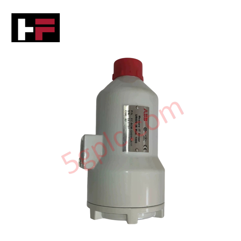
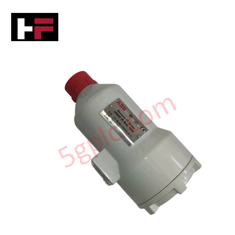
Tech & Buying Guide

Transforming Shop Floor Data into Actionable Insights: A Deep Dive into MES
Manufacturing Execution Systems serve as the digital backbone of modern factory floors. Positioned at Level 3 of the ISA-95 automation pyramid, MES links enterprise resource planning with real-time shop floor control systems. Today, industrial operators rely on MES software to bridge operational strategy with physical production execution.

Managed Switch vs. Unmanaged Switch: Industrial Ethernet Architecture

Hot Standby vs. Cold Standby Redundancy in Industrial Automation
System availability determines process safety and productivity in industrial automation. Control engineers deploy redundancy to eliminate single points of failure. This technical guide evaluates Hot Standby vs. Cold Standby architectures, comparing failover speeds, memory sync, cost trade-offs, and field selection criteria.