










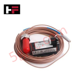
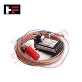
Product Details
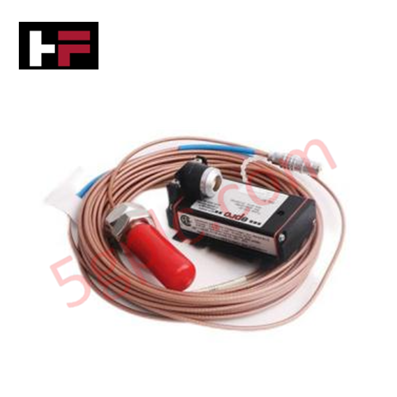
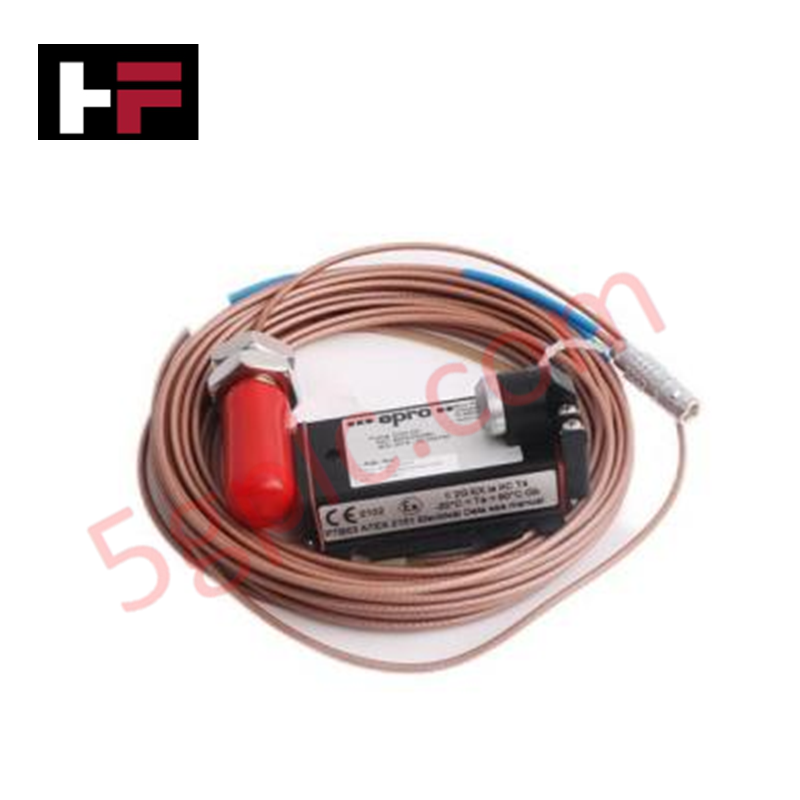
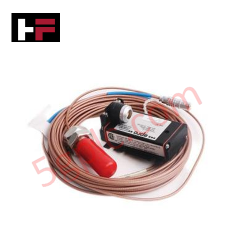
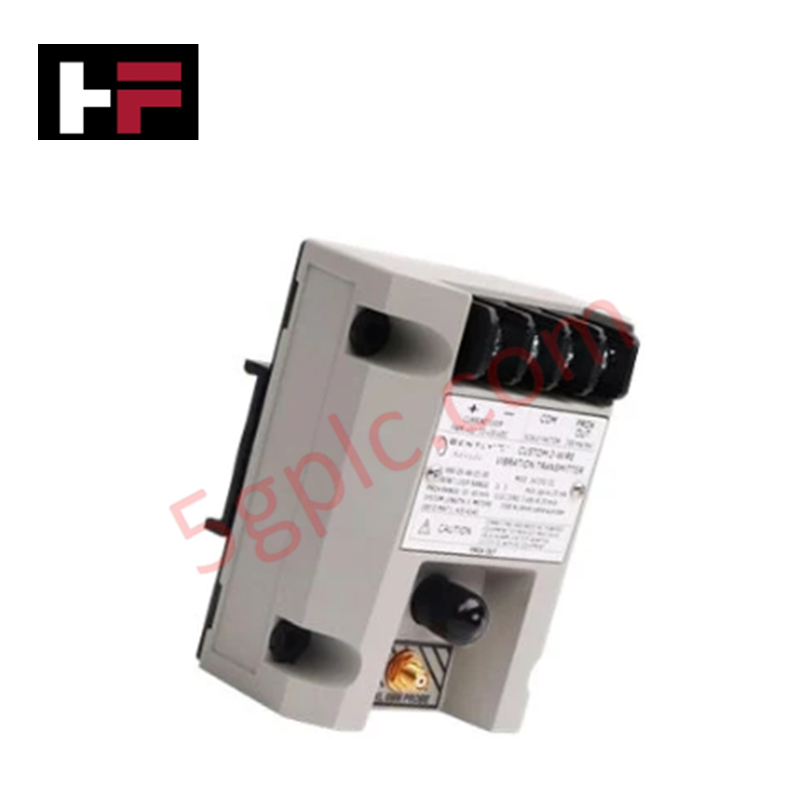
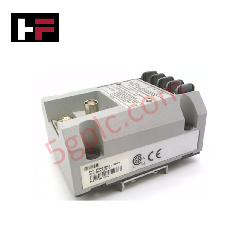
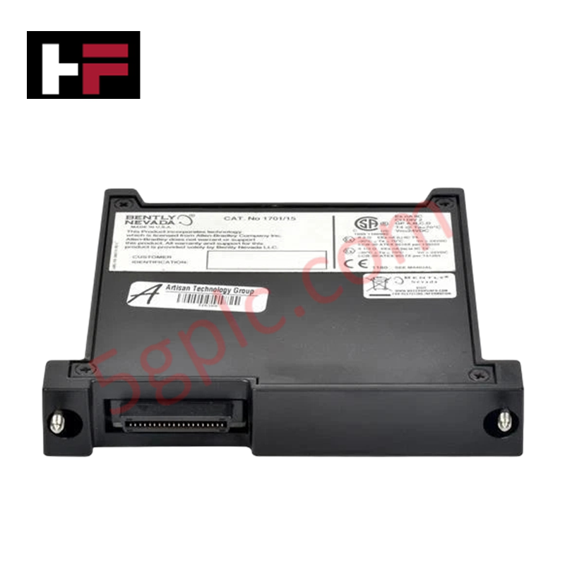
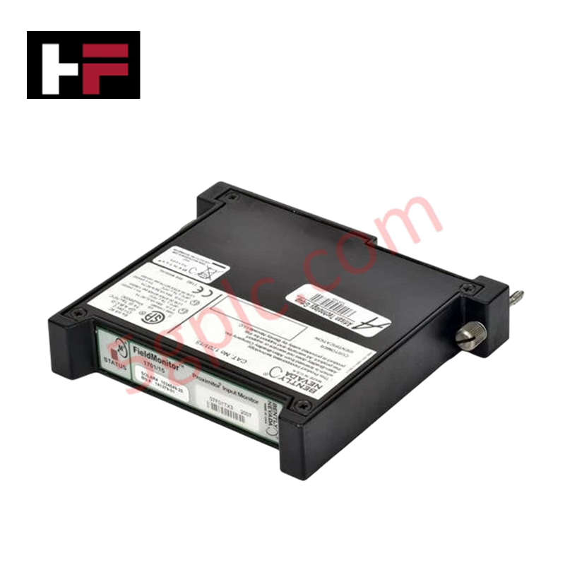
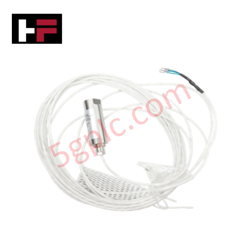
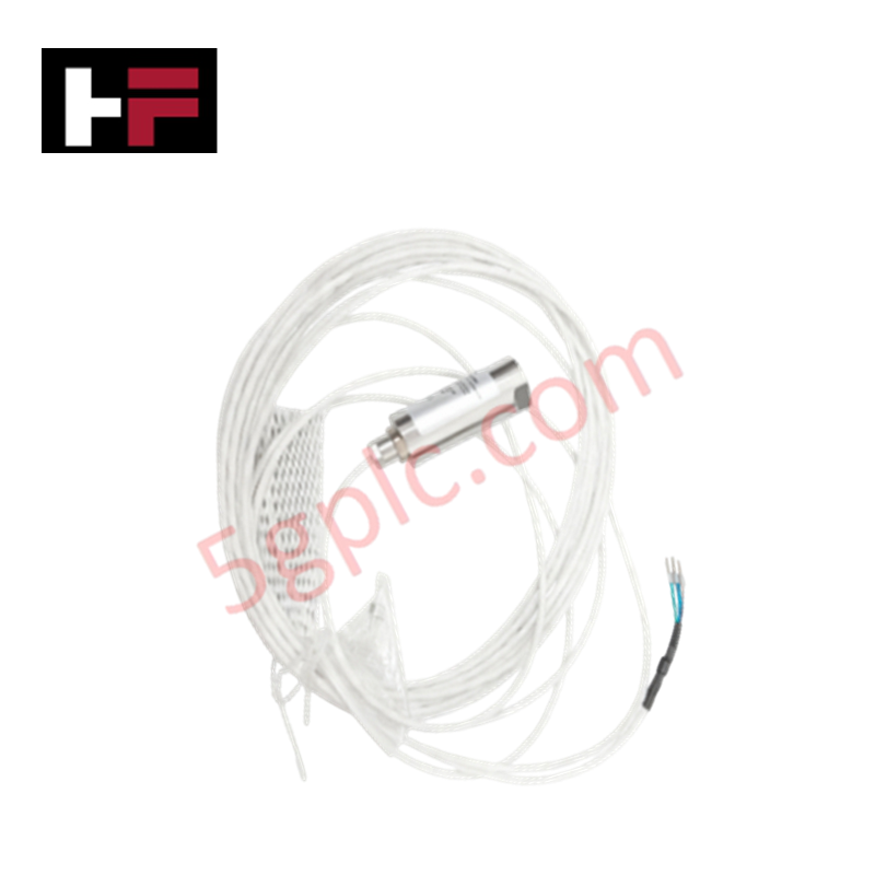
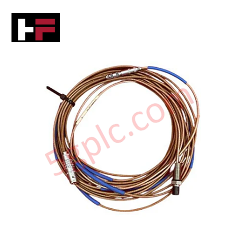
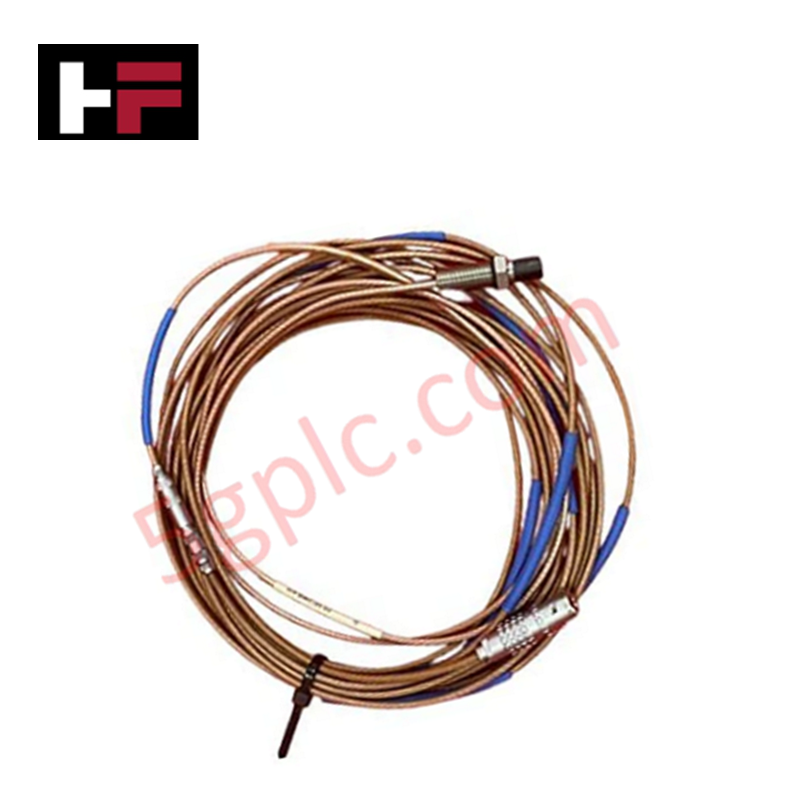
The Emerson PR6424/003-030 CON021, also cataloged as the PR6424 / CON021 Eddy Current Sensor, operates as a dedicated hardware component for non-contact shaft displacement and vibration measurement within turbomachinery protection platforms. The sensing system generates a high-frequency electromagnetic field at the probe tip to detect microscopic gaps between the sensor face and target conductive metal surfaces. The associated converter conditions this physical proximity response into a proportional continuous analog output signal for direct processing by machinery monitoring systems.
Hardware Specifications
| Parameter | Specification |
|---|---|
| Model | PR6424/003-030 CON021 |
| Brand | Emerson |
| Origin | United States |
| Weight | 0.32 kg |
| Dimensions | 12.1 cm * 5.2 cm * 16.6 cm |
| Operating Temp | -30 to +80 deg C (Converter) / -35 to +180 deg C (Probe head) |
| Power Consumption | < 1.2 W (at nominal supply voltage) |
| Measuring Principle | Eddy Current Inductive Proximity |
| Output Signal Range | 4-20 mA HART loop protocol / Raw Gap Voltage |
| Target Calibration | Ferromagnetic Steel (42CrMo4 / AISI 4140) |
| Channel Isolation | Galvanic signal isolation to supply power |
4-20 mA HART Loop Protocol & Signal Conditioning
The integrated converter circuit employs a 4-20 mA HART loop protocol to transmit primary dynamic displacement variables alongside internal diagnostic field data over standard two-wire connections. Galvanic channel-to-channel isolation prevents ground loop currents from distorting high-frequency displacement signals during multi-channel bearing rack operations. Analog output scaling maintains predictable linearity across the target measuring range, minimizing total loop noise and thermal drift over prolonged continuous operation.
Frequently Asked Questions
Q: What power supply arrangement is required to power the signal converter?
A: The converter requires an external 24 VDC power supply connected via shielded twisted-pair cabling. Loop power must remain within specified operating voltage thresholds to ensure stable oscillator output.
Q: How does loop shield termination affect signal integrity?
A: Signal cable shielding must be connected to functional earth at a single point, typically at the monitoring cabinet terminal frame, to avoid dual-ground potential differences and loop noise.
Field Installation Guidelines
Mount the probe tip securely using designated bracketry, ensuring a minimum side-wall clearance of 1.5 times the tip diameter to eliminate extraneous metal interference. Route sensor cables through dedicated grounded metal conduits separated from high-voltage motor supply wiring. Tighten all cable connectors finger-tight plus one-quarter turn to maintain environmental sealing, and apply self-amalgamating tape over external outdoor joints. Maintain a minimum bend radius of 30 mm along extension cables during field installation.
Additional Information
- 100% Genuine Parts: All products are original and authentic, ensuring reliable industrial performance.
- 30-Day Refund Guarantee: Return any in-stock item within 30 days in original, unopened packaging for a full refund (excluding shipping and fees).
- 12-Month Warranty: Covers defects in materials or workmanship; excludes misuse, normal wear, or unauthorized modifications.
- Worldwide Shipping: We ship via USPS, UPS, FedEx, and DHL. Delivery times vary by country and may be subject to customs or import fees.
- Support & Contact: Technical and warranty assistance is available anytime. Contact us here: Contact.
- Purchase Guidance: Check product specifications and compatibility carefully before ordering to ensure proper application.
Tech & Buying Guide
Demystifying the 5 Levels of Industrial Automation Architecture
Modern manufacturing relies on structured communication hierarchy to bridge physical shop-floor hardware with enterprise management software. This framework, commonly known as the Automation Pyramid, establishes how data flows between field devices, logic controllers, and corporate IT networks. Understanding these five distinct levels helps engineers and plant managers optimize system operations, reduce downtime, and implement seamless factory automation solutions.

Transforming Shop Floor Data into Actionable Insights: A Deep Dive into MES
Manufacturing Execution Systems serve as the digital backbone of modern factory floors. Positioned at Level 3 of the ISA-95 automation pyramid, MES links enterprise resource planning with real-time shop floor control systems. Today, industrial operators rely on MES software to bridge operational strategy with physical production execution.
