










Product Details
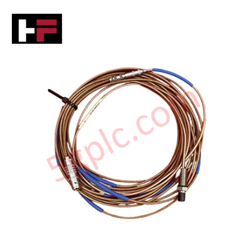
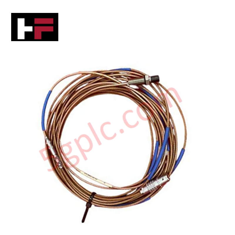
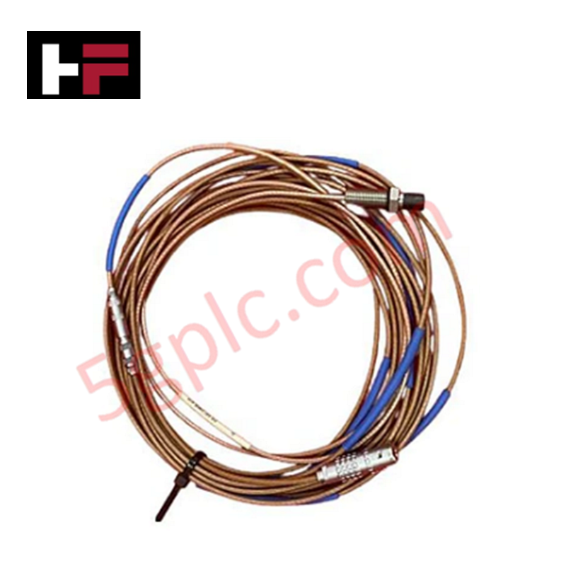
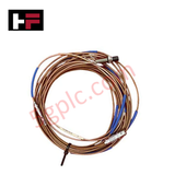
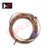
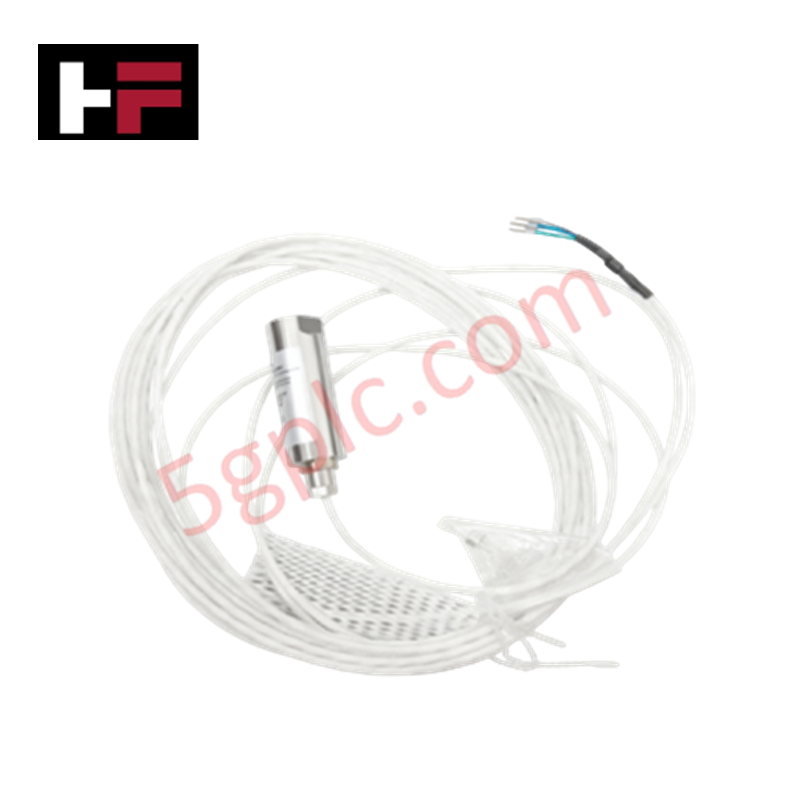
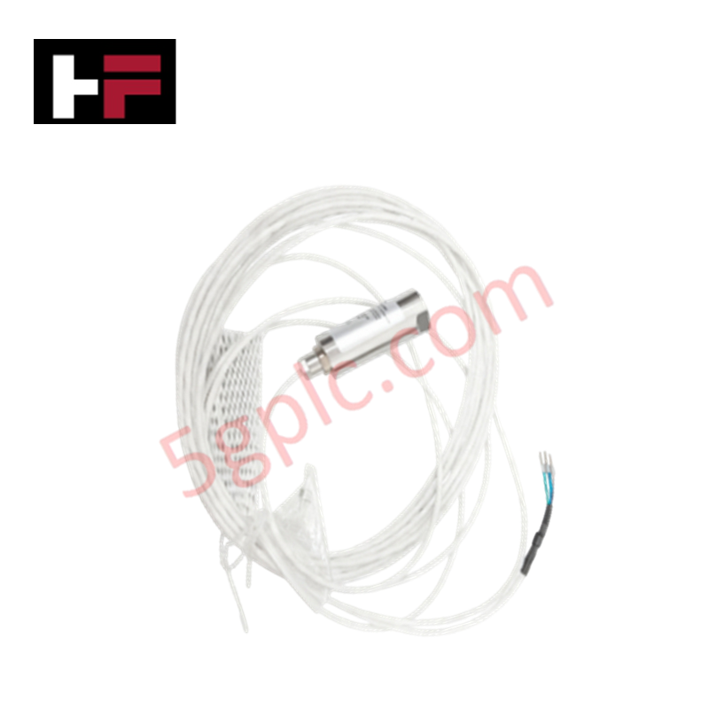
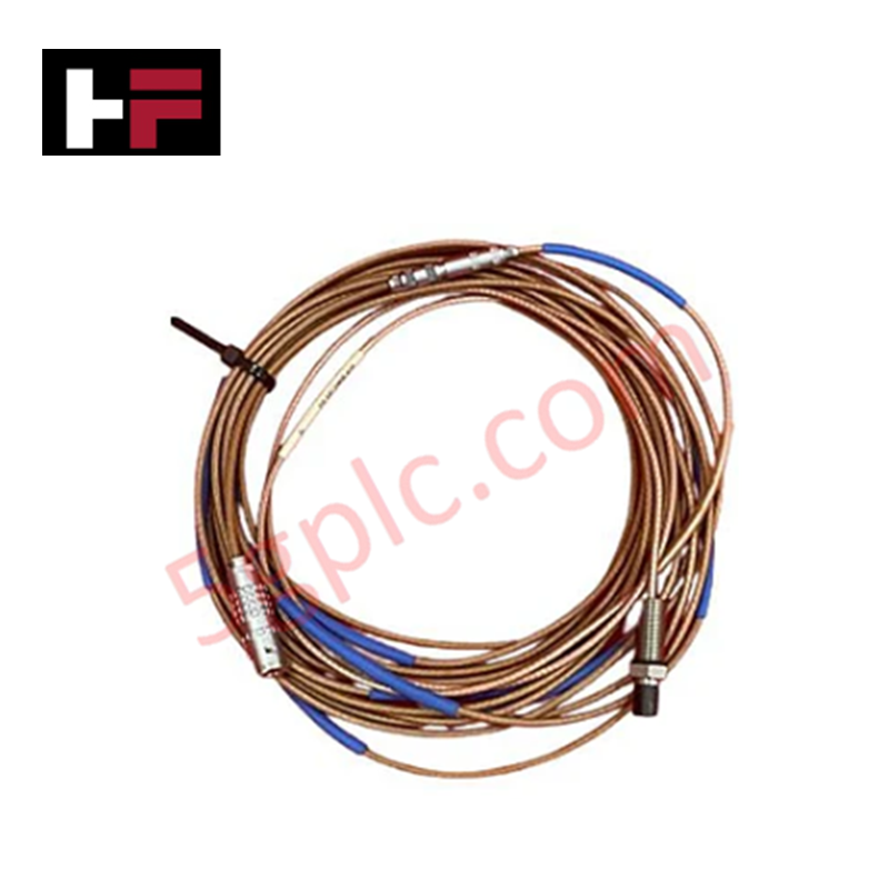
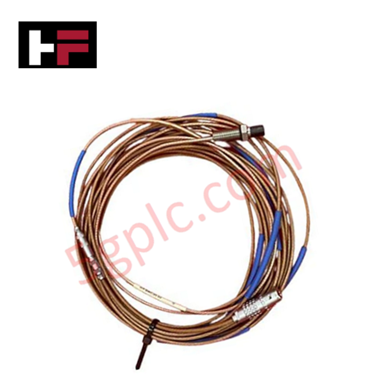
Configured for non-contact measurement of radial and axial shaft vibration and dynamic position, the Emerson Epro PR6423/10R-131-CN (PR6423/10R-131-CN Eddy Current Sensor) provides direct physical signal execution. This transducer detects target impedance variations to generate high-resolution analog voltage signals for real-time diagnostic evaluation of rotating machinery.
Hardware Specifications
| Parameter | Specification |
|---|---|
| Model | PR6423/10R-131-CN |
| Brand | Emerson (Epro) |
| Origin | Subject to certificate of origin |
| Weight | 0.1 kg |
| Dimensions | 8 mm Sensor diameter |
| Operating Temp | -35 deg C to +200 deg C |
| Power Consumption | Dependent on interface converter |
| Measurement Range | 2 mm |
| Scale Factor | 8 V/mm (203.2 mV/mil) |
| Protection Class | IP66 |
Eddy-Current Probe Scaling and Rotor Dynamics
Measurement integrity of the Emerson Epro PR6423/10R-131-CN is inherently linked to proper probe scaling relative to the AISI 4140 ferromagnetic shaft target. To maintain the linear output characteristics defined by the Incremental Scale Factor, the sensor must be installed at a nominal 0.5 mm air gap. Validation of the gap voltage is required during commissioning to ensure the probe operates within the linear segment of the transducer curve. Effective rotor dynamics monitoring further necessitates strict cross-talk suppression by maintaining sufficient physical separation between adjacent probes, preventing interference from overlapping carrier frequency magnetic fields.
Frequently Asked Questions
Q: Is this sensor compatible with target materials other than ferromagnetic steel?
A: No, the sensor is factory-calibrated exclusively for 42CrMo4 or AISI 4140 steel. Using materials with different magnetic permeability or electrical conductivity will introduce non-linearities and degrade measurement accuracy.
Q: Can the cable length be modified without recalibrating the system?
A: No, the sensor and cable act as a tuned circuit. Modifying the cable length alters the capacitive and inductive load, which shifts the carrier frequency and necessitates recalibration of the signal converter.
Q: What is the risk of operating the sensor tip beyond the 200 deg C limit?
A: Exposure to temperatures exceeding 200 deg C will cause thermal degradation of the PEEK tip and the internal coil potting, leading to signal instability, calibration drift, and premature failure of the hermetic seal.
Field Installation Guidelines
- Mounting: Secure the sensor in a rigid, vibration-isolated bracket using the stainless steel threaded body. Ensure the sensor face is perpendicular to the shaft centerline to prevent geometric error.
- Grounding: Route signal cables through grounded metallic conduit. Terminate the cable shield at a single, dedicated instrument ground terminal to minimize ground loops and high-frequency noise.
- Gap Adjustment: Use a non-conductive feeler gauge to set the 0.5 mm initial air gap. Verify the output voltage at the converter terminal before locking the installation nuts.
- Environment: Ensure the connector is housed within an enclosure compliant with IP66 or higher, protected from direct spray or hazardous atmospheric particulates.
Additional Information
- 100% Genuine Parts: All products are original and authentic, ensuring reliable industrial performance.
- 30-Day Refund Guarantee: Return any in-stock item within 30 days in original, unopened packaging for a full refund (excluding shipping and fees).
- 12-Month Warranty: Covers defects in materials or workmanship; excludes misuse, normal wear, or unauthorized modifications.
- Worldwide Shipping: We ship via USPS, UPS, FedEx, and DHL. Delivery times vary by country and may be subject to customs or import fees.
- Support & Contact: Technical and warranty assistance is available anytime. Contact us here: Contact.
- Purchase Guidance: Check product specifications and compatibility carefully before ordering to ensure proper application.
Tech & Buying Guide
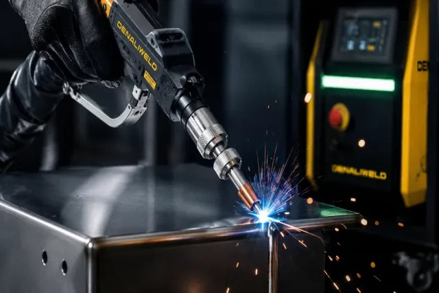
Demystifying the 5 Levels of Industrial Automation Architecture
Modern manufacturing relies on structured communication hierarchy to bridge physical shop-floor hardware with enterprise management software. This framework, commonly known as the Automation Pyramid, establishes how data flows between field devices, logic controllers, and corporate IT networks. Understanding these five distinct levels helps engineers and plant managers optimize system operations, reduce downtime, and implement seamless factory automation solutions.

Transforming Shop Floor Data into Actionable Insights: A Deep Dive into MES
Manufacturing Execution Systems serve as the digital backbone of modern factory floors. Positioned at Level 3 of the ISA-95 automation pyramid, MES links enterprise resource planning with real-time shop floor control systems. Today, industrial operators rely on MES software to bridge operational strategy with physical production execution.
