











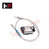
Product Details
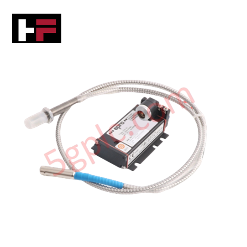
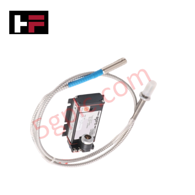
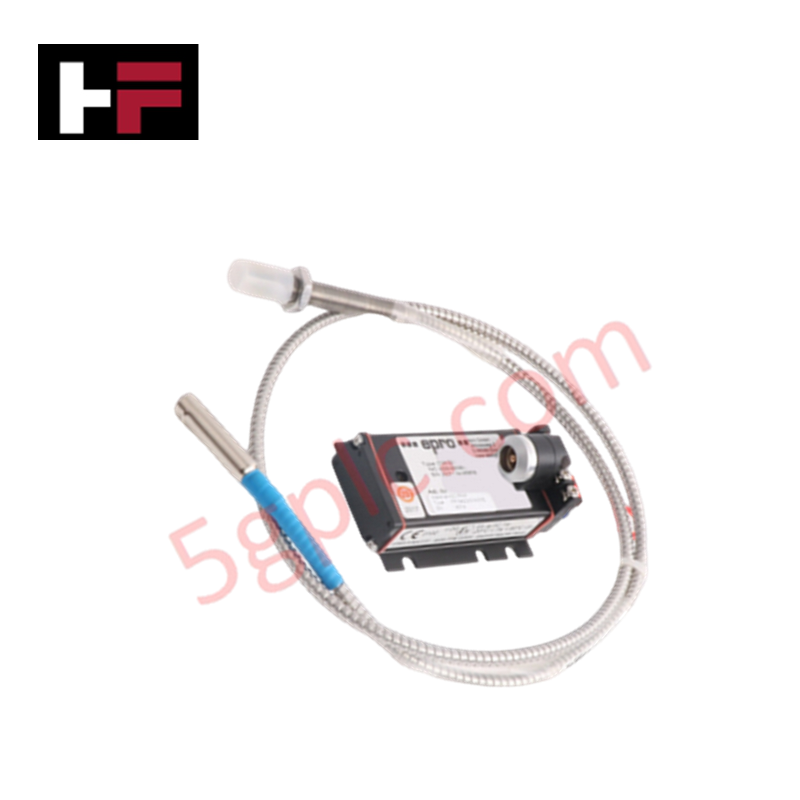
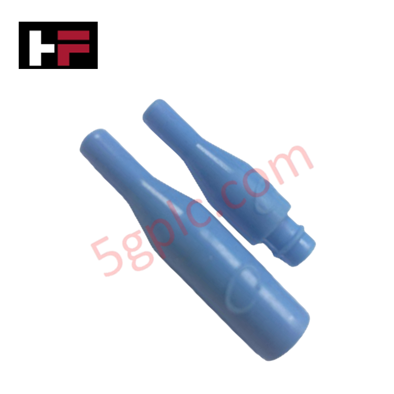
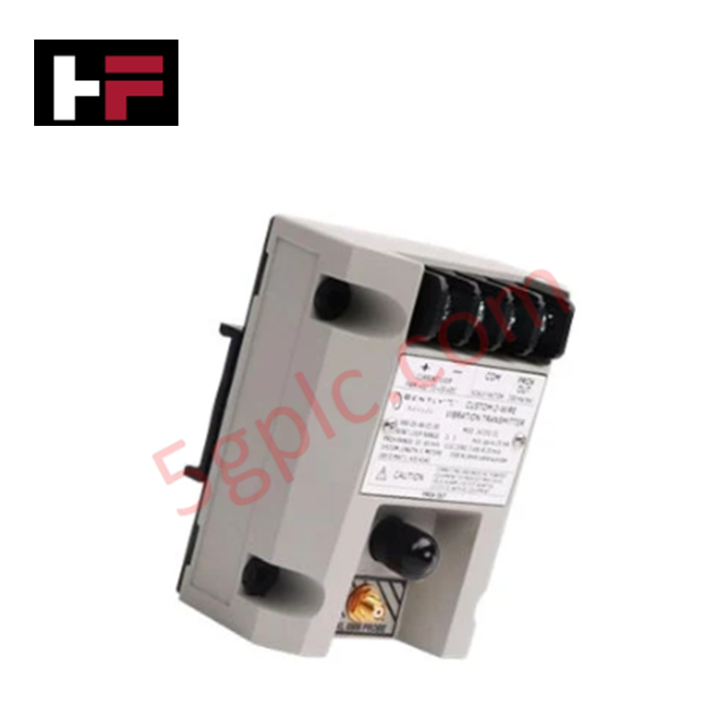
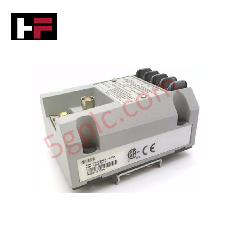
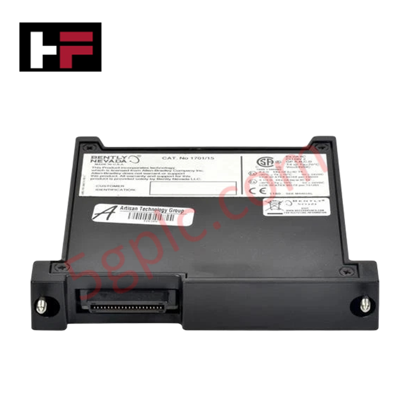
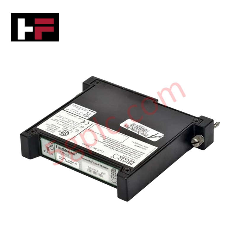
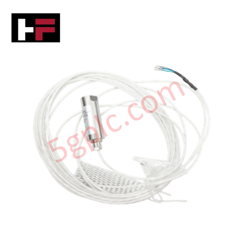
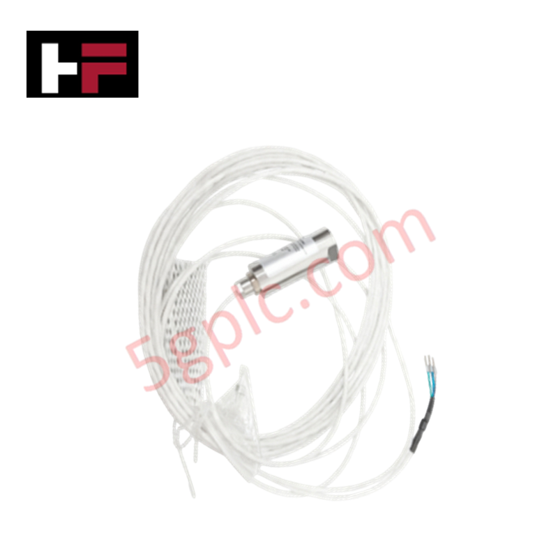
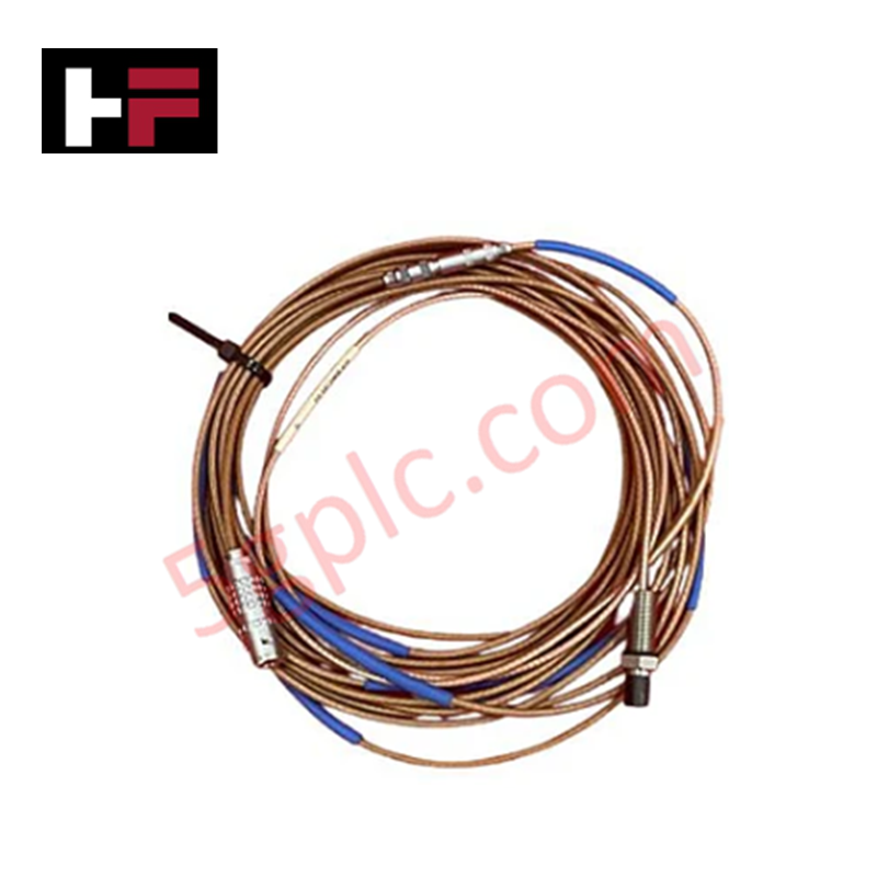
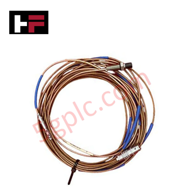
Configured for non-contact shaft vibration and displacement measurement in Emerson machinery monitoring systems, the Emerson CON021+PR6424/007-110-CN (CON021 / PR6424 Eddy Current Sensor) provides direct physical/electrical execution. The hardware assembly pairs a stainless steel inductive proximity transducer probe with a signal conditioning converter unit to measure physical gaps between the sensor tip and conductive metal targets. High-frequency electromagnetic oscillations generate eddy currents in the target material, producing an analog output current proportional to static position and dynamic vibration amplitude.
Hardware Specifications
| Parameter | Specification |
|---|---|
| Model | CON021+PR6424/007-110-CN |
| Brand | Emerson |
| Origin | United States |
| Operating Temp | -35 to +180 deg C (Sensor Head) |
| Power Consumption | 0.48 W (20 mA at 24 VDC) |
| Supply Voltage | 24 VDC |
| Measurement Range | 0 to 7 mm |
| Resolution | 0.1 mm |
| Output Signal | 4-20 mA |
| Shell Material | Stainless Steel |
| Cable Length | 2 m |
| Ingress Protection | IP67 |
4-20 mA HART Loop Protocol & Channel Isolation
The signal conditioning converter utilizes internal galvanic channel-to-channel isolation to decouple supply ground potentials from signal measuring paths, preventing ground loop interference across multi-channel protection racks. The scaled analog front-end processes proximity frequency shifts and converts distance deviations into a continuous 4-20 mA loop protocol current. Built-in thermal sensing circuits provide temperature compensation across the -35 to +180 deg C operating window, stabilizing signal calibration slopes and preventing bias drifts during continuous thermal cycles.
Frequently Asked Questions
Q: How is thermal calibration drift minimized across wide field temperature fluctuations?
A: The probe assembly incorporates internal temperature compensation circuitry rated across -35 to +180 deg C, maintaining calibrated 4-20 mA output response linearity during thermal expansion cycles.
Q: Is live hot-swapping permitted for the signal converter or probe extension cables?
A: RF connections between probe and converter must not be altered while loop power is applied; always isolate the 24 VDC power feed prior to disconnecting coaxial cable fittings to prevent signal offset errors.
Field Installation Guidelines
Ensure minimum lateral clearance of 1.5 times the probe tip diameter from adjacent housing walls to eliminate uncalibrated side-wall eddy current damping. Route the 2 m integrated cable through grounded, rigid metal conduit separated from AC power and variable frequency drive lines. Connect cable shielding to functional technical ground at a single cabinet earth point to avoid potential ground loops. Torque probe mounting thread nuts to standard specifications and seal exposed outdoor connectors using self-amalgamating silicone tape to maintain the IP67 ingress protection rating.
Additional Information
- 100% Genuine Parts: All products are original and authentic, ensuring reliable industrial performance.
- 30-Day Refund Guarantee: Return any in-stock item within 30 days in original, unopened packaging for a full refund (excluding shipping and fees).
- 12-Month Warranty: Covers defects in materials or workmanship; excludes misuse, normal wear, or unauthorized modifications.
- Worldwide Shipping: We ship via USPS, UPS, FedEx, and DHL. Delivery times vary by country and may be subject to customs or import fees.
- Support & Contact: Technical and warranty assistance is available anytime. Contact us here: Contact.
- Purchase Guidance: Check product specifications and compatibility carefully before ordering to ensure proper application.
Tech & Buying Guide

Transforming Shop Floor Data into Actionable Insights: A Deep Dive into MES
Manufacturing Execution Systems serve as the digital backbone of modern factory floors. Positioned at Level 3 of the ISA-95 automation pyramid, MES links enterprise resource planning with real-time shop floor control systems. Today, industrial operators rely on MES software to bridge operational strategy with physical production execution.

Managed Switch vs. Unmanaged Switch: Industrial Ethernet Architecture

Hot Standby vs. Cold Standby Redundancy in Industrial Automation
System availability determines process safety and productivity in industrial automation. Control engineers deploy redundancy to eliminate single points of failure. This technical guide evaluates Hot Standby vs. Cold Standby architectures, comparing failover speeds, memory sync, cost trade-offs, and field selection criteria.