










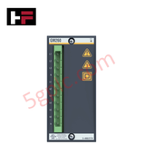
Product Details
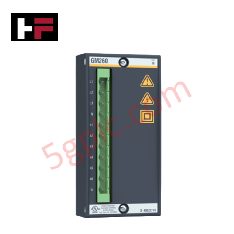
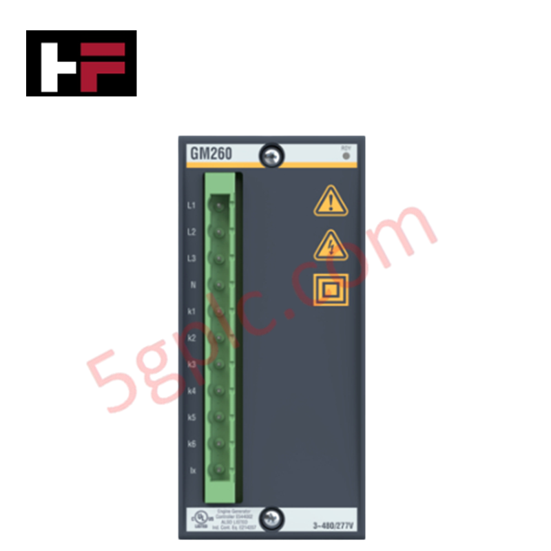
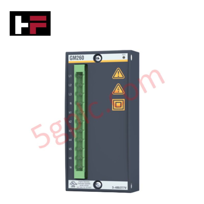
Configured for high-speed electrical network monitoring in M1 control platforms, the Bachmann GM260 (GM260 Grid Measurement Module) provides direct data acquisition of three-phase network variables.
Hardware Specifications
| Parameter | Specification |
|---|---|
| Model | GM260 |
| Brand | Bachmann |
| Origin | Austria |
| Dimensions | Standard Bachmann module enclosure |
| Input Capacity | 2 separate three-phase branches |
| Max Input Voltage | 480 VAC (L-L) RMS |
| Harmonics Analysis | Up to 40th harmonic |
Profinet / EtherNet/IP Deterministic Networks
The GM260 module utilizes integrated processing to calculate True RMS grid variables online, ensuring the data provided to the deterministic network is cycle-time consistent. By computing harmonics up to the 40th order directly on the module, the load on the host CPU is minimized, facilitating efficient backplane bus communication velocity. The module integrates seamlessly with Bachmann SolutionCenter, allowing real-time access to active, apparent, and reactive power metrics. Firmware flash compatibility ensures that the grid calculation algorithms remain updated, providing accurate 4-quadrant energy counting within the M1 control environment.
Frequently Asked Questions
Q: Does the GM260 require external transducers for voltage measurement?
A: No. The module is designed to accept direct connections of input voltages up to 480 VAC (L-L) RMS, eliminating the need for intermediate voltage transducers in standard applications.
Q: How are energy values tracked within the module?
A: The module features 2 independent 4-quadrant (4Q) energy counters that are processed internally, ensuring precise energy monitoring without requiring external processing cycles.
Field Installation Guidelines
- Ensure all voltage and current connections are made in accordance with the local electrical safety standards and the module pinout diagram.
- Verify that the CT (Current Transformer) ratios are correctly configured in the SolutionCenter to ensure accurate current and power calculations.
- Utilize shielded cabling for all measurement inputs to prevent electromagnetic noise from interfering with the high-frequency harmonics sampling.
- Confirm that the common voltage monitoring point is correctly referenced to ground to prevent potential measurement offsets between the two three-phase branches.
- Perform an initial commissioning test using the SolutionCenter interface to verify that phase angles and RMS values align with secondary multimeter readings.
Additional Information
- 100% Genuine Parts: All products are original and authentic, ensuring reliable industrial performance.
- 30-Day Refund Guarantee: Return any in-stock item within 30 days in original, unopened packaging for a full refund (excluding shipping and fees).
- 12-Month Warranty: Covers defects in materials or workmanship; excludes misuse, normal wear, or unauthorized modifications.
- Worldwide Shipping: We ship via USPS, UPS, FedEx, and DHL. Delivery times vary by country and may be subject to customs or import fees.
- Support & Contact: Technical and warranty assistance is available anytime. Contact us here: Contact.
- Purchase Guidance: Check product specifications and compatibility carefully before ordering to ensure proper application.







Tech & Buying Guide

Demystifying the 5 Levels of Industrial Automation Architecture
Modern manufacturing relies on structured communication hierarchy to bridge physical shop-floor hardware with enterprise management software. This framework, commonly known as the Automation Pyramid, establishes how data flows between field devices, logic controllers, and corporate IT networks. Understanding these five distinct levels helps engineers and plant managers optimize system operations, reduce downtime, and implement seamless factory automation solutions.

Transforming Shop Floor Data into Actionable Insights: A Deep Dive into MES
Manufacturing Execution Systems serve as the digital backbone of modern factory floors. Positioned at Level 3 of the ISA-95 automation pyramid, MES links enterprise resource planning with real-time shop floor control systems. Today, industrial operators rely on MES software to bridge operational strategy with physical production execution.
