


Product Details
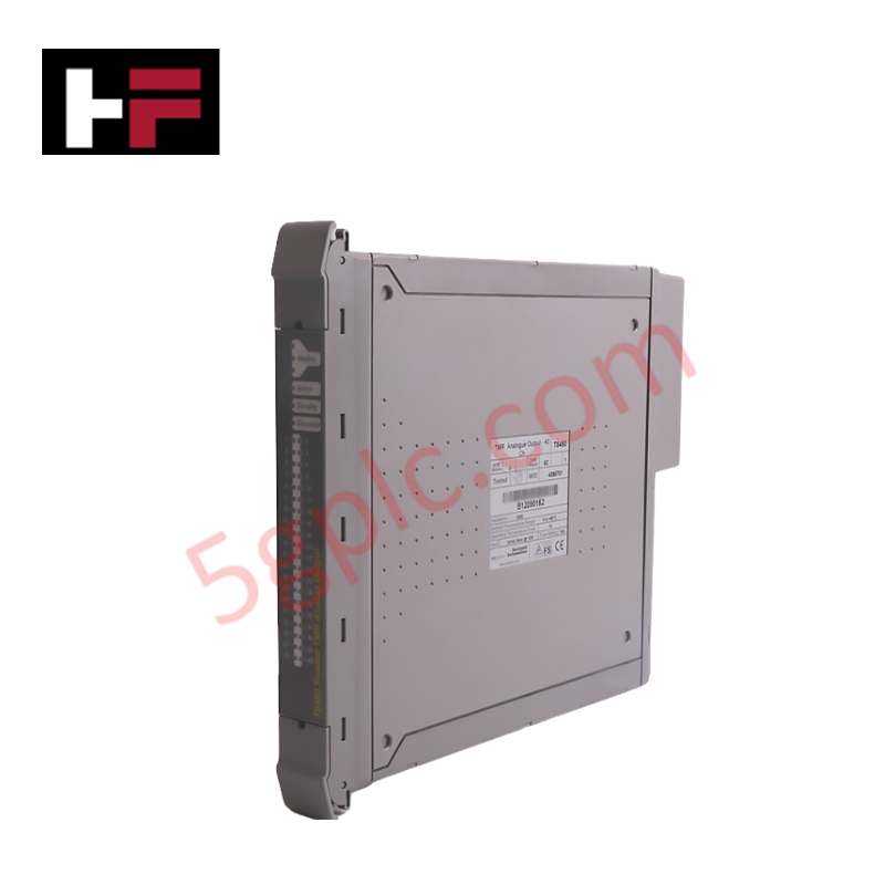
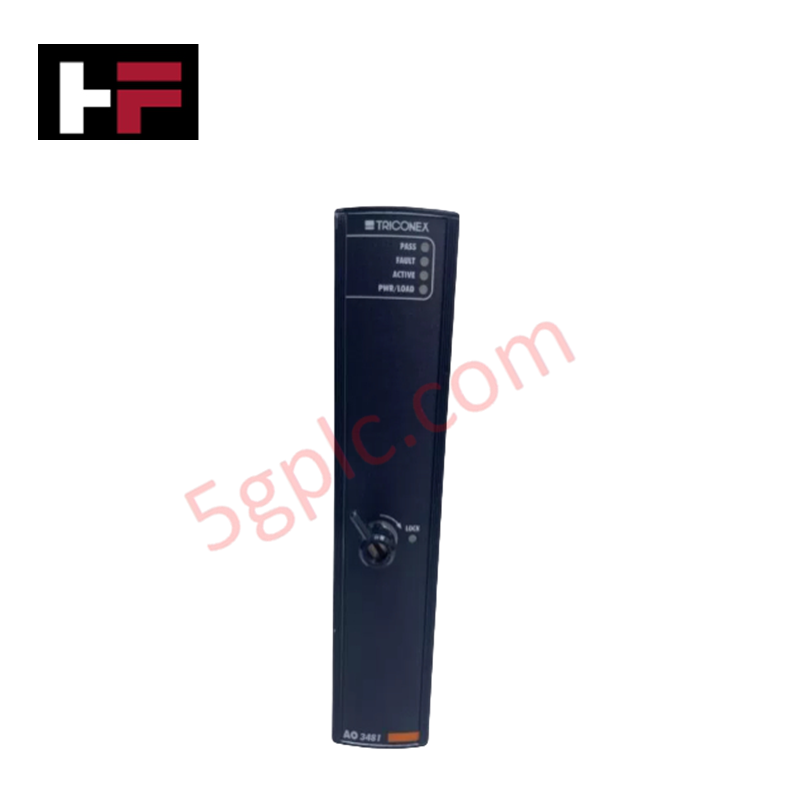
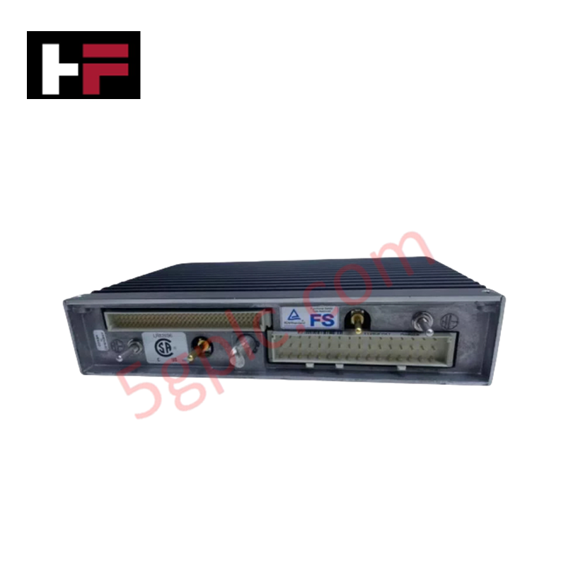
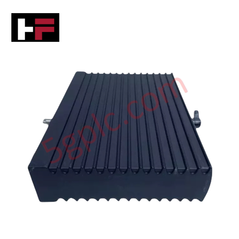
Configured for precise signal control in Schneider Electric Triconex safety instrumented systems, the Triconex AO3481 S2 (AO3481 S2 Analog Output Module) provides direct physical/electrical execution. It converts internal digital system commands into 8 programmable analog current and voltage control loops for final field elements such as valves and actuators via the TSAA communication protocol.
Hardware Specifications
| Parameter | Specification |
|---|---|
| Model | AO3481 S2 |
| Brand | Triconex (Schneider Electric) |
| Origin | USA |
| Weight | 0.6 kg |
| Dimensions | 76.2 mm x 118.1 mm x 12.7 mm |
| Operating Temp | -20 deg C to +70 deg C |
| Power Consumption | Operating Voltage: 24 VDC; Max Output Current: 6.5 A |
| Output Channels | 8 programmable channels |
| Output Signal Range | 4-20 mA, 0-10 V, 0-5 V |
| Resolution | 16-bit |
| Accuracy | < 0.25% full scale |
| Protection Rating | IP20 |
Triple Modular Redundancy (TMR) 2oo3 Architecture and Galvanic Isolation
The Triconex AO3481 S2 executes command processing within a triple modular redundancy (TMR) 2oo3 architecture to guarantee continuous system availability and fail-safe state execution. Each of the 8 output channels utilizes triple parallel circuits that vote on command signals before driving field devices, ensuring that a single hardware fault cannot compromise the output loop. Complete channel-to-channel galvanic isolation prevents field-side electrical surges or ground loops from propagating to the active backplane logic bus.
Frequently Asked Questions
Q: Does the AO3481 S2 module support hot-swap replacement while the main chassis remains powered?
A: Yes, the module supports online hot-swapping into an active chassis slot without interrupting adjacent module operation or disrupting system backplane communication.
Q: How does the triple modular redundancy architecture execute fail-safe state actions on a loop failure?
A: Internal hardware voting mechanisms continuously monitor output integrity; if an unresolvable hardware channel mismatch or loss of backplane communication occurs, the module defaults to a pre-programmed fail-safe output state.
Q: What power parameters are required to drive the 8 analog output loops on the module?
A: The module requires an external 24 VDC field power supply to drive loop currents up to a maximum total rating of 6.5 A across its 8 channels.
Field Installation Guidelines
- Align the module card edge connectors with the designated slot in the Triconex main chassis and push firmly until the retention mechanism fully engages.
- Connect field signal wiring to the corresponding external termination panel (ETP) screw terminals, observing correct polarity for 4-20 mA or voltage loops.
- Route analog field loop cabling through grounded metallic wireways, maintaining physical separation from high-voltage AC power conductors.
- Ensure shield wires are bonded to the dedicated system instrumentation ground point at the panel terminal rail to eliminate high-frequency noise interference.
Additional Information
- 100% Genuine Parts: All products are original and authentic, ensuring reliable industrial performance.
- 30-Day Refund Guarantee: Return any in-stock item within 30 days in original, unopened packaging for a full refund (excluding shipping and fees).
- 12-Month Warranty: Covers defects in materials or workmanship; excludes misuse, normal wear, or unauthorized modifications.
- Worldwide Shipping: We ship via USPS, UPS, FedEx, and DHL. Delivery times vary by country and may be subject to customs or import fees.
- Support & Contact: Technical and warranty assistance is available anytime. Contact us here: Contact.
- Purchase Guidance: Check product specifications and compatibility carefully before ordering to ensure proper application.

Tech & Buying Guide

Managed Switch vs. Unmanaged Switch: Industrial Ethernet Architecture

Hot Standby vs. Cold Standby Redundancy in Industrial Automation
System availability determines process safety and productivity in industrial automation. Control engineers deploy redundancy to eliminate single points of failure. This technical guide evaluates Hot Standby vs. Cold Standby architectures, comparing failover speeds, memory sync, cost trade-offs, and field selection criteria.