


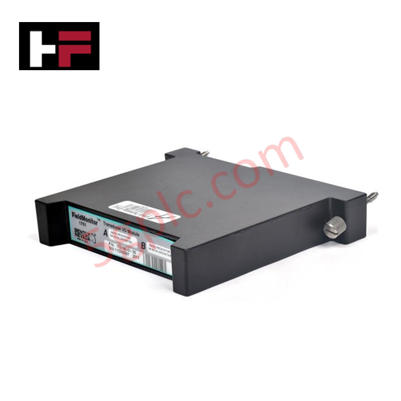
Product Details
Configured for discrete signal execution in DeltaV control platforms, the Emerson VE4002S1T2B3 (VE4002S1T2B3 Discrete Output Module) provides direct physical/electrical control via 8 high-side output channels.
Hardware Specifications
| Parameter | Specification |
|---|---|
| Model | VE4002S1T2B3 |
| Brand | Emerson |
| Origin | Not specified |
| Weight | 3.00 lbs |
| Power Consumption | 24 VDC |
| Channel Count | 8 Channels |
Process Control and DCS Connectivity
The VE4002S1T2B3 module utilizes channel-to-channel isolation to prevent propagation of electrical faults between individual output circuits. This design ensures that a localized short circuit or overcurrent condition on one channel does not compromise the operational integrity of remaining channels. Integration with the DeltaV control network is managed through the I/O bus, which provides real-time status feedback for each discrete point. The architecture supports 4-20 mA HART loop protocol compatibility on associated analog channels within the same I/O subsystem, ensuring consistent field instrumentation diagnostics across the process environment.
Frequently Asked Questions
Q: Does the module support hot-swapping under power?
A: Yes, this module is designed for insertion and removal while the I/O subsystem is energized (hot-swap). Ensure the system is configured to handle the state transition of field outputs to a safe condition before removing the module from the carrier.
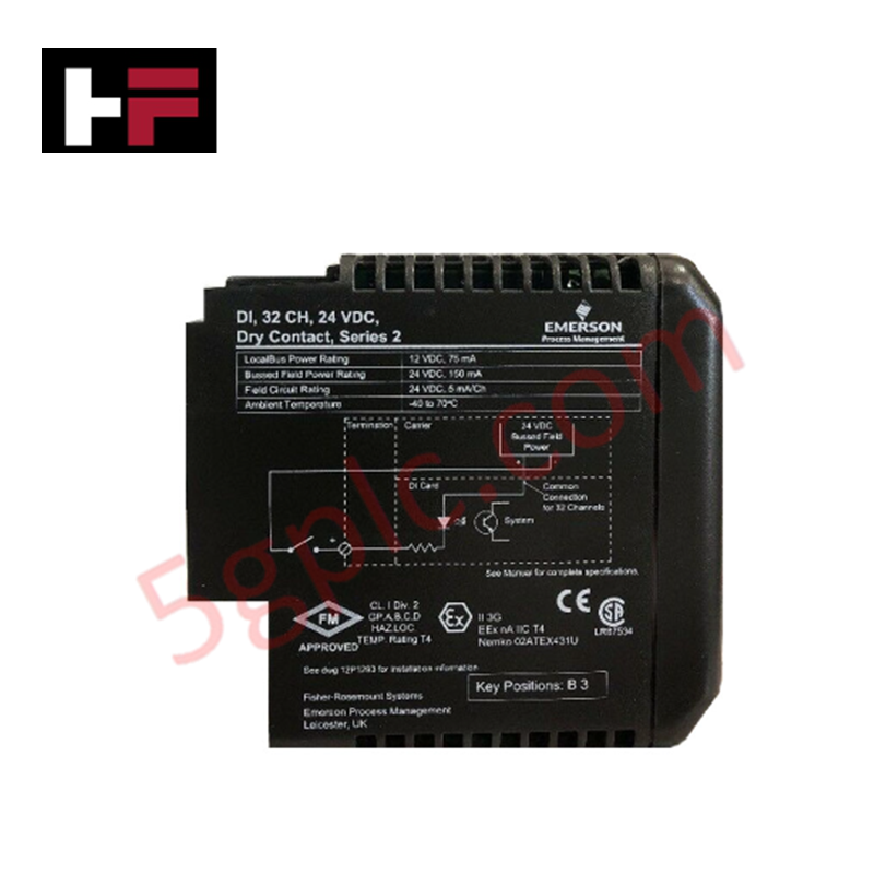
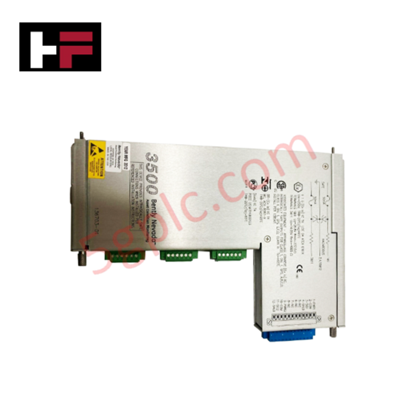
Q: What is the purpose of the 16-pin mass termination block?
A: The 16-pin mass termination block facilitates rapid field wiring connection to the I/O module. It serves as the physical interface for all 8 discrete output channels, allowing for efficient cable management and consistent point-to-point electrical contact.
Field Installation Guidelines
- Mounting: Install the module onto the designated I/O carrier. Ensure the carrier is properly secured to the mounting rail and the backplane connector is aligned to prevent pin damage during insertion.
- Termination: Utilize the 16-pin mass termination block for field wiring. Strip wires to the manufacturer-specified length and secure them firmly in the terminal block to ensure low-resistance electrical contact.
- Grounding: Ensure the I/O carrier is bonded to a clean earth ground to maintain signal integrity and provide a path for surge suppression.
- Verification: After installation, utilize the system engineering station to perform a loop check. Confirm that the module diagnostics report clear channel status and that field devices respond according to the commanded output state.
Additional Information
- 100% Genuine Parts: All products are original and authentic, ensuring reliable industrial performance.
- 30-Day Refund Guarantee: Return any in-stock item within 30 days in original, unopened packaging for a full refund (excluding shipping and fees).
- 12-Month Warranty: Covers defects in materials or workmanship; excludes misuse, normal wear, or unauthorized modifications.
- Worldwide Shipping: We ship via USPS, UPS, FedEx, and DHL. Delivery times vary by country and may be subject to customs or import fees.
- Support & Contact: Technical and warranty assistance is available anytime. Contact us here: Contact.
- Purchase Guidance: Check product specifications and compatibility carefully before ordering to ensure proper application.


Tech & Buying Guide

Understanding Types of Noise in Electronic Circuits and Control Systems
Signal integrity directly determines measurement accuracy and loop stability across industrial automation environments. Electronic noise introduces unwanted stochastic interference into analog loops, sensor feedback lines, and digital fieldbus networks. Understanding how intrinsic electronic noise and external electromagnetic interference manifest allows control engineers to optimize signal conditioning and shield sensitive instrumentation effectively.

Why 24V DC Power Supplies Standardize Modern Industrial Automation
Industrial control cabinets worldwide rely on 24V DC as the universal power standard for field instrumentation, sensors, and controllers. Walk into any manufacturing plant, and you will find PLCs, human-machine interfaces (HMIs), and smart actuators running on extra-low voltage DC. Standardizing on 24V DC enhances operational safety, lowers cabinet footprint, and maintains steady control performance across factory networks.

Essential Motion Control Commands: A Practical Guide for Engineers
Automation engineers often rely on precise position and speed control to drive modern factory machinery. Modern industrial systems, such as Programmable Logic Controllers (PLCs) and Distributed Control Systems (DCS), depend heavily on standardized motion instructions. Mastering these commands ensures operational safety, protects mechanical components, and optimizes cycle times across production lines.