








Product Details
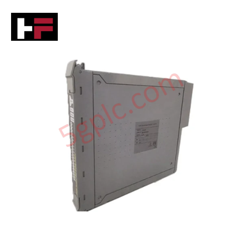
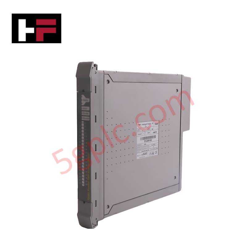
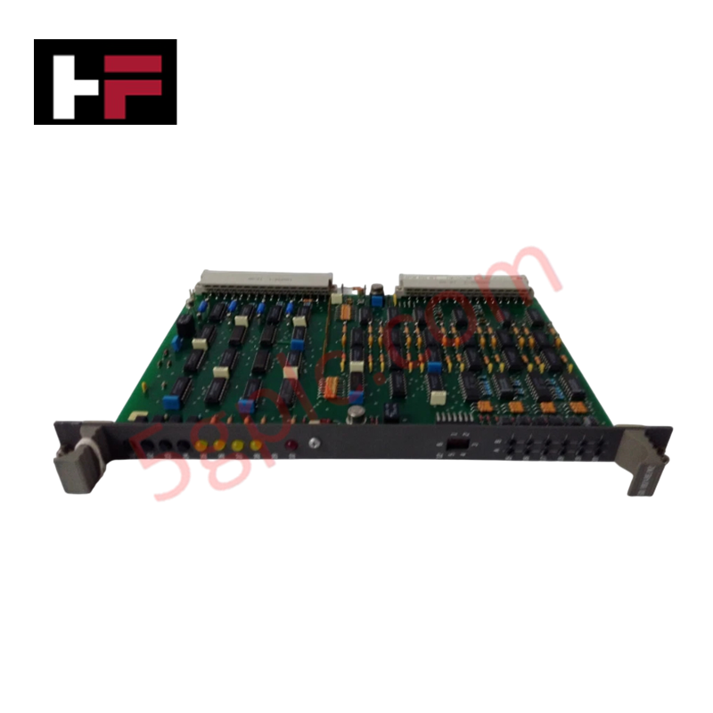
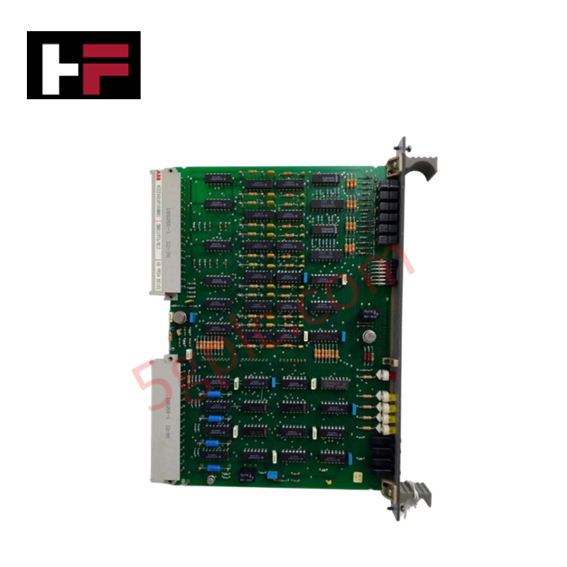
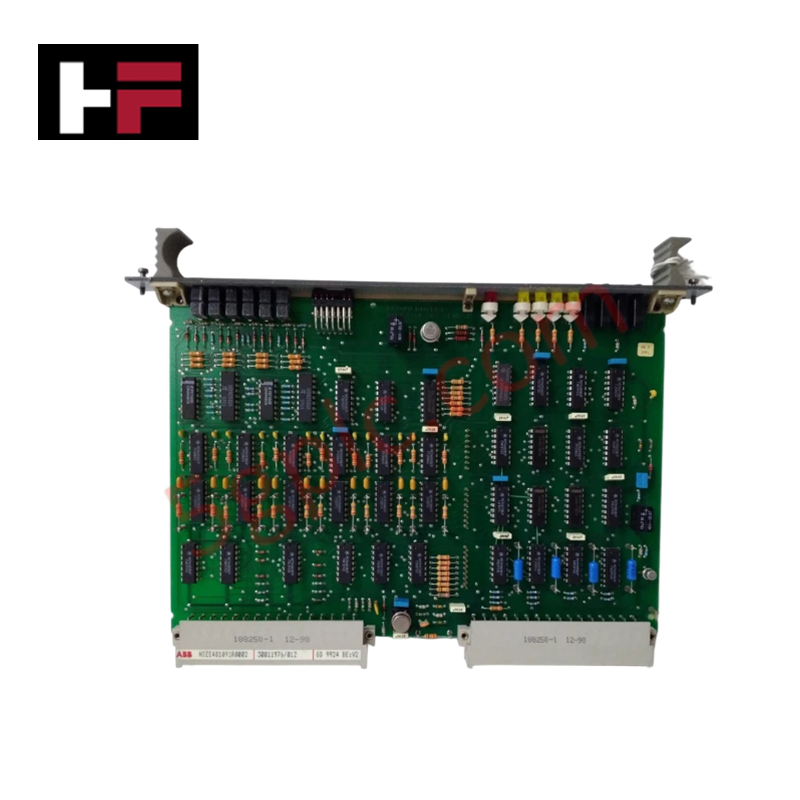
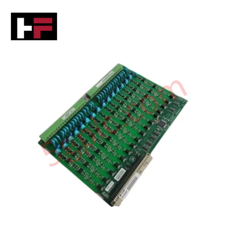
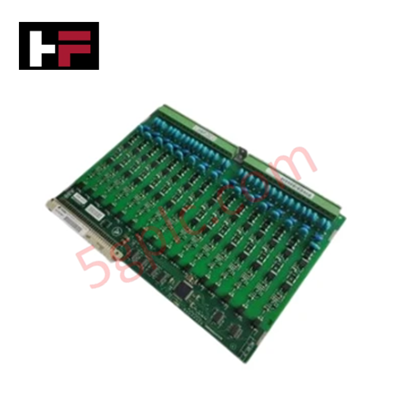
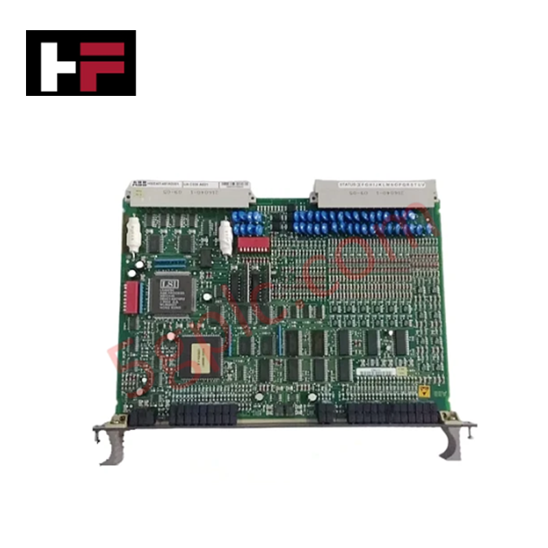
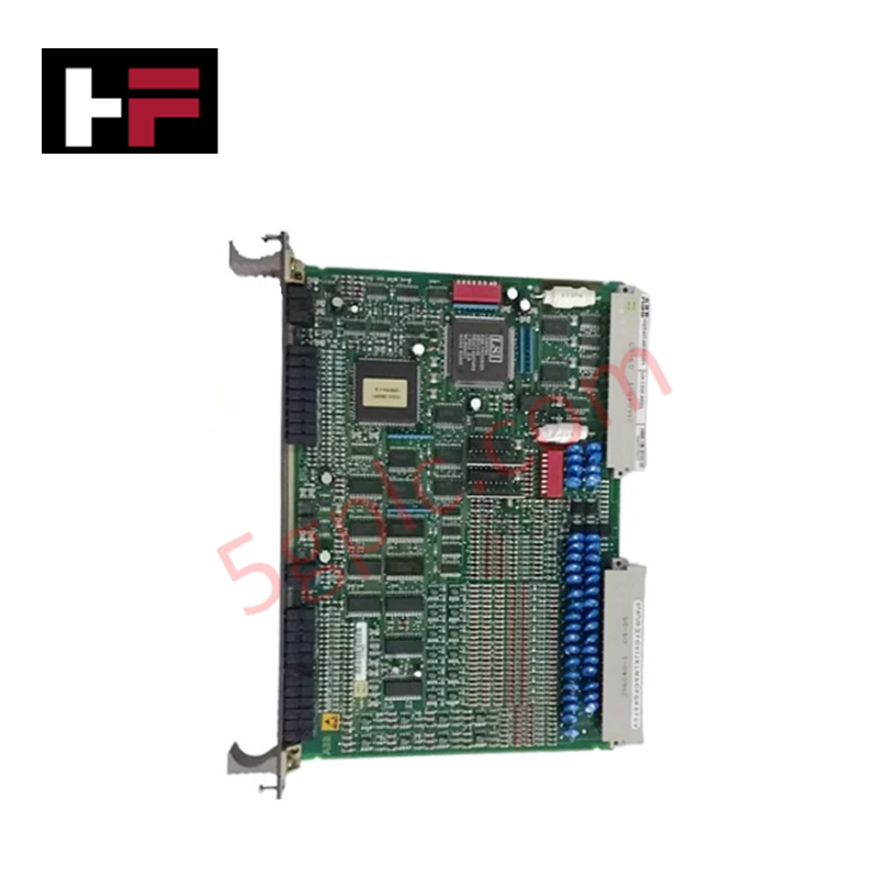
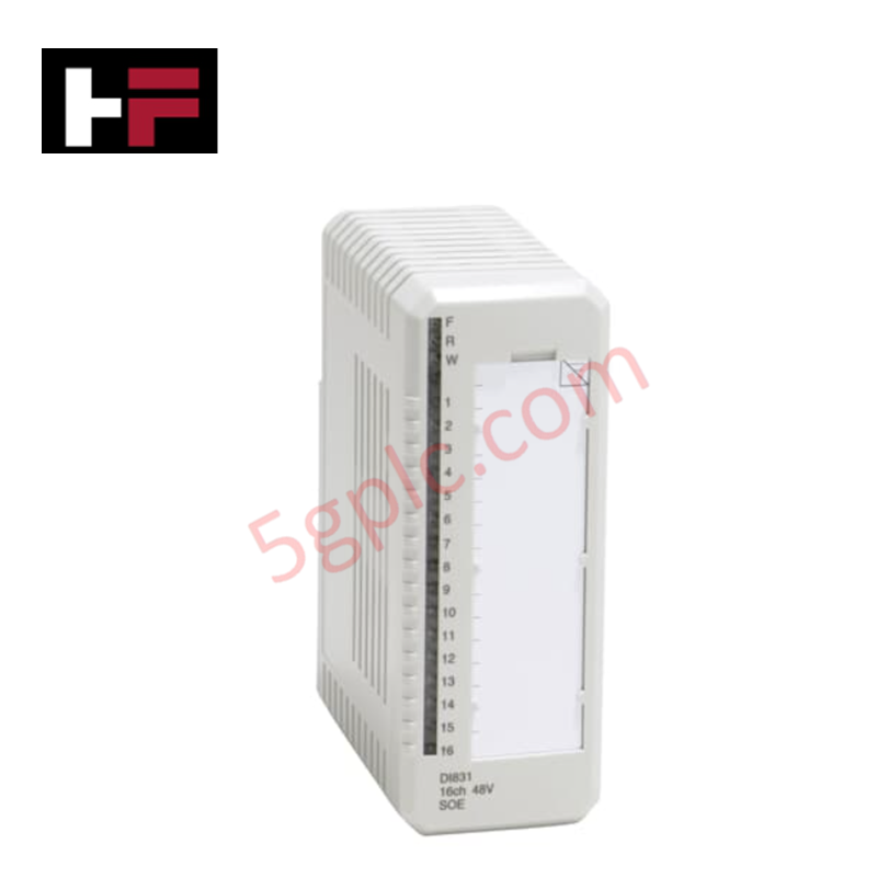
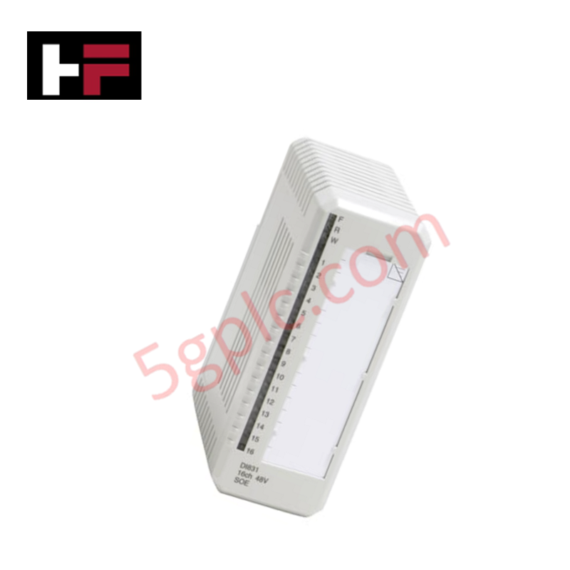
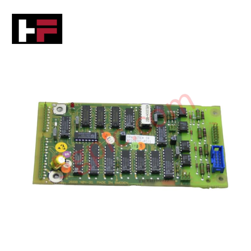
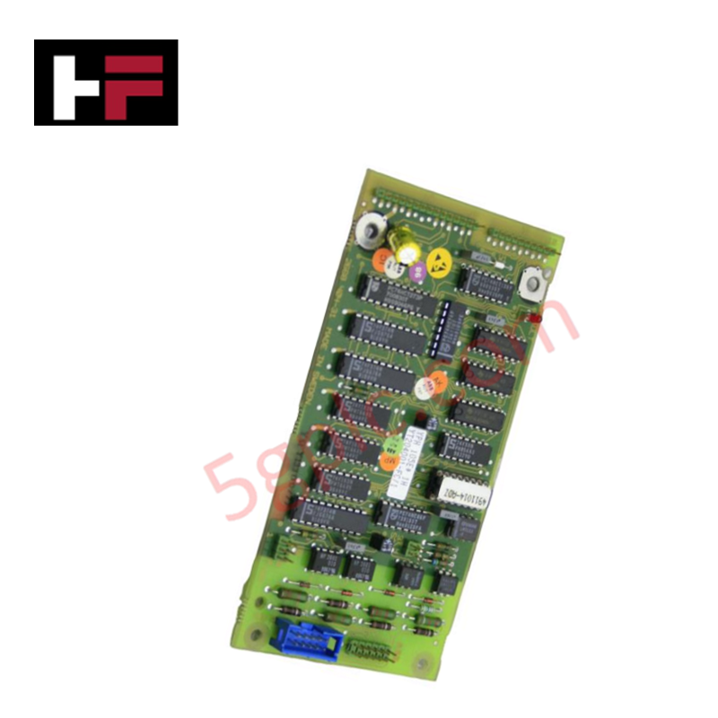
The ABB GD9924BE,V2 HIEE401091R0002, also cataloged as the GD9924BE,V2 Digital Input Module, operates as a dedicated hardware component for high-speed discrete state acquisition and signal isolation within RobotWare controller architectures.
Hardware Specifications
| Parameter | Specification |
|---|---|
| Model | GD9924BE,V2 |
| Part Number | HIEE401091R0002 |
| Brand | ABB |
| Origin | Sweden |
| Weight | 1.05 kg |
| Dimensions (L x W x H) | 38.2 cm x 12.7 cm x 6.0 cm |
| Operating Temp | 0 to 55 deg C |
| Power Consumption | Backplane bus powered |
| Module Type | Scalable Digital Input Module |
| Electrical Isolation | Galvanic isolation per channel group |
| Network Topology | Dual-port integrated switch for daisy chaining |
| Signal Processing | Change of State (CoS) fast signal detection |
| Mounting Support | Standard DIN-rail / Controller internal mount |
Backplane Bus Communication Velocity & I/O Density Scaling
The GD9924BE,V2 integrates a dual-port Ethernet switch interface to facilitate daisy-chain network topologies across scalable I/O nodes without additional hardware switches. Supporting deterministic bus communication velocity through Change of State (CoS) triggering, the module transmits field input status changes immediately across the backplane bus to minimize controller response latencies. Galvanic isolation across input channels protects internal processing circuits from field-side voltage transients and loop interference, while maintaining high I/O density scaling inside control cabinets.
Frequently Asked Questions
Q: Does the GD9924BE,V2 support daisy-chain network configurations?
A: Yes. The module includes an integrated dual-port Ethernet switch that enables direct daisy-chaining between adjacent I/O units, reducing cable routing requirements within or outside the controller cabinet.
Q: How does Change of State (CoS) signal processing function on this digital input module?
A: Rather than relying solely on fixed cyclical polling, Change of State logic immediately triggers data transmissions upon detecting an input state transition, accelerating signal transfer speeds to the master controller.
Field Installation Guidelines
- Mounting: Snap the module firmly onto a standard 35 mm DIN rail inside the controller cabinet or at a distributed external junction box. Ensure the DIN-rail locking mechanism is fully engaged.
- Wiring Isolation: Route digital input signal cables through dedicated wire channels separated from high-voltage AC motor power lines to minimize induced electromagnetic noise.
- Network Cabling: Connect Ethernet cables to the dual-port switch interfaces using shielded RJ45 connectors. Verify that minimum cable bend radius limits are respected during installation.
- Grounding: Connect the module chassis shielding to the main functional earth (FE) bus bar using low-impedance grounding connections to maintain galvanic isolation performance.
Additional Information
- 100% Genuine Parts: All products are original and authentic, ensuring reliable industrial performance.
- 30-Day Refund Guarantee: Return any in-stock item within 30 days in original, unopened packaging for a full refund (excluding shipping and fees).
- 12-Month Warranty: Covers defects in materials or workmanship; excludes misuse, normal wear, or unauthorized modifications.
- Worldwide Shipping: We ship via USPS, UPS, FedEx, and DHL. Delivery times vary by country and may be subject to customs or import fees.
- Support & Contact: Technical and warranty assistance is available anytime. Contact us here: Contact.
- Purchase Guidance: Check product specifications and compatibility carefully before ordering to ensure proper application.
Tech & Buying Guide

Preventing Emergency Stop Spurious Trips in Industrial Control Systems
Emergency Stop pushbuttons use Normally Closed contacts for fail-safe safety, but mechanical wear can cause costly spurious trips. This technical guide examines E-Stop contact failure root causes, redundant hardware setups, PLC logic monitoring, and maintenance strategies to maximize plant availability.

Why 24V DC Is the Universal Standard for Industrial Automation Power Supplies
Industrial manufacturing requires continuous uptime to prevent equipment damage. Unlike AC power, 24V DC circuits seamlessly integrate with UPS units and battery banks. During main grid failures, a 24V DC backup system instantly maintains PLC memory, instrument loops, and critical safety valves without interruption.

Site Acceptance Testing (SAT) for PLC Control Systems: An Engineering Execution Guide
The Site Acceptance Test (SAT) represents the definitive handover stage in industrial automation projects. While the Factory Acceptance Test confirms cabinet hardware assembly off-site, the SAT validates real-world performance under live site conditions. Consequently, a structured execution strategy prevents equipment damage and guarantees seamless integration into plant operations.