










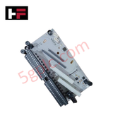
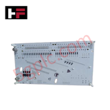
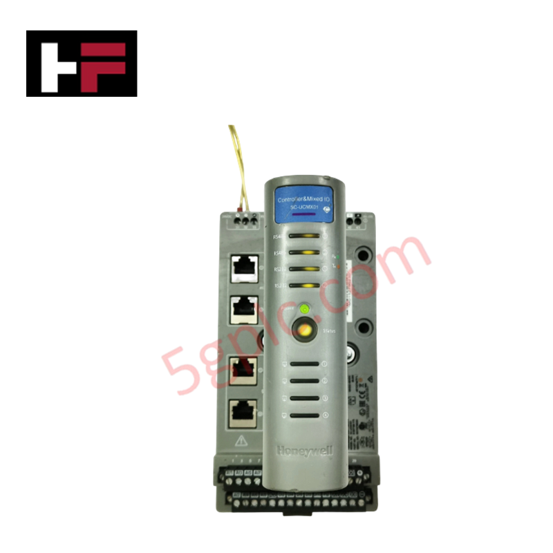
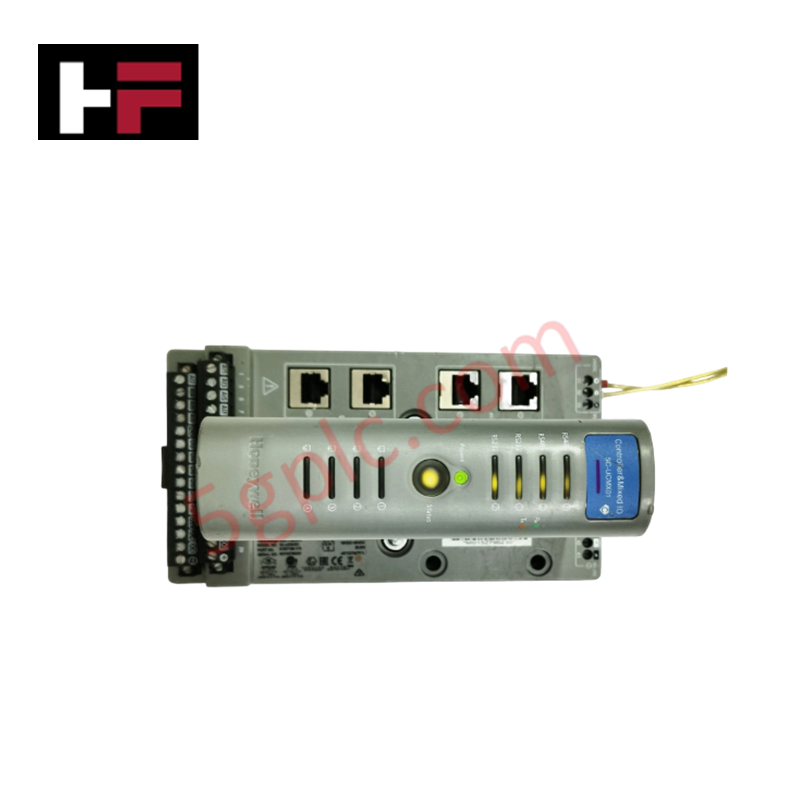
Product Details
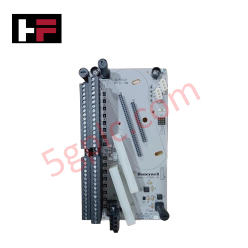
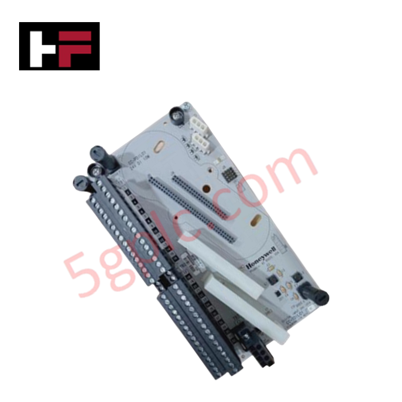
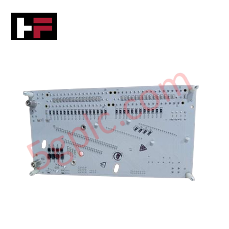
Configured for discrete signal acquisition in control system networks, the Honeywell DC-TDIL01 (DC-TDIL01 Digital Input Module) provides direct physical and electrical execution of multi-voltage logic monitoring. The module serves as the primary digital input interface utilized to execute field state detection across Honeywell control platforms.
Hardware Specifications
| Parameter | Specification |
|---|---|
| Model | DC-TDIL01 |
| Brand | Honeywell |
| Origin | USA |
| Weight | 0.4 kg |
| Dimensions | 110 x 16 x 82 mm |
| Operating Temp | 0 to 60 deg C |
| Power Consumption | Not Specified |
| Input Signal Levels | 5, 12, 24, 48, 60 VDC |
| Isolation | 250 Vrms |
Process Control and Signal Connectivity
The DC-TDIL01 module is engineered to accommodate variable voltage thresholds, supporting system integration across diverse field device requirements. The unit features 250 Vrms channel-to-channel isolation to prevent potential high-voltage feedback from field-side shorts or surges into the control backplane. Configurable for either positive or negative logic, the module adapts to existing site wiring standards without additional hardware modifications. The internal signal processing chain is optimized for a 1 ms typical response time, ensuring deterministic status reporting for critical process interlocks and alarm sequences.
Frequently Asked Questions
Q: Does the DC-TDIL01 module support hot-swapping under load?
A: No. The module is not designed for hot-swapping. Removal or insertion while the backplane is powered may cause bus transient errors or trigger an I/O fault, potentially impacting the operational state of the associated controller.
Q: How is the logic polarity (positive/negative) configured for this module?
A: Logic configuration is handled through the module's internal settings or the system controller's I/O mapping software. Ensure the physical field wiring matches the software-defined logic polarity to prevent inverted state detection.
Field Installation Guidelines
- De-energize the input module rack and isolate field power sources before attempting installation.
- Ensure the DIN-rail or rack mounting surface is clean and provides a solid mechanical ground for the module chassis.
- Align the module with the rack backplane connector; insert firmly until the mechanical locking mechanism engages to ensure full contact.
- Terminate field signal wires according to the established site schematics, ensuring that cable shielding is bonded to the designated common ground to minimize electromagnetic interference (EMI).
- Verify signal state changes using the system diagnostic interface to confirm correct field-to-logic mapping before commissioning the control loops.
Additional Information
- 100% Genuine Parts: All products are original and authentic, ensuring reliable industrial performance.
- 30-Day Refund Guarantee: Return any in-stock item within 30 days in original, unopened packaging for a full refund (excluding shipping and fees).
- 12-Month Warranty: Covers defects in materials or workmanship; excludes misuse, normal wear, or unauthorized modifications.
- Worldwide Shipping: We ship via USPS, UPS, FedEx, and DHL. Delivery times vary by country and may be subject to customs or import fees.
- Support & Contact: Technical and warranty assistance is available anytime. Contact us here: Contact.
- Purchase Guidance: Check product specifications and compatibility carefully before ordering to ensure proper application.
Tech & Buying Guide

Transforming Shop Floor Data into Actionable Insights: A Deep Dive into MES
Manufacturing Execution Systems serve as the digital backbone of modern factory floors. Positioned at Level 3 of the ISA-95 automation pyramid, MES links enterprise resource planning with real-time shop floor control systems. Today, industrial operators rely on MES software to bridge operational strategy with physical production execution.

Managed Switch vs. Unmanaged Switch: Industrial Ethernet Architecture

Hot Standby vs. Cold Standby Redundancy in Industrial Automation
System availability determines process safety and productivity in industrial automation. Control engineers deploy redundancy to eliminate single points of failure. This technical guide evaluates Hot Standby vs. Cold Standby architectures, comparing failover speeds, memory sync, cost trade-offs, and field selection criteria.