










Product Details
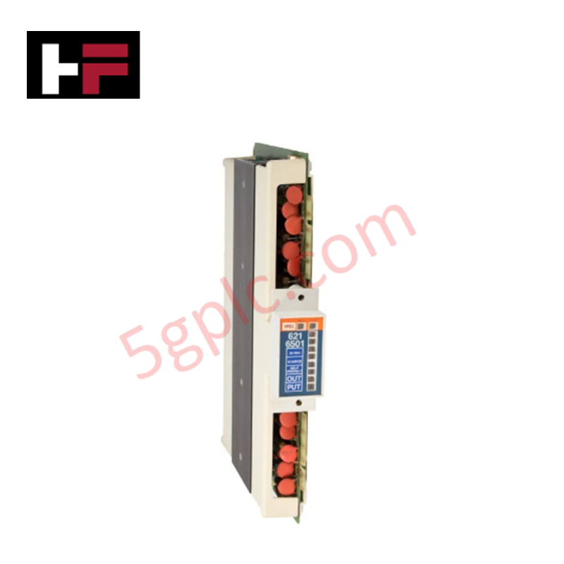
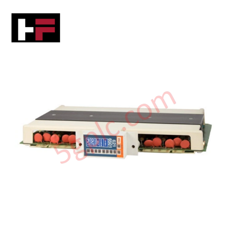
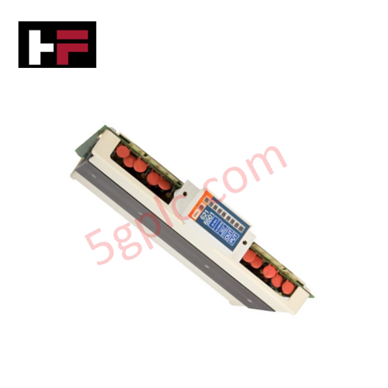
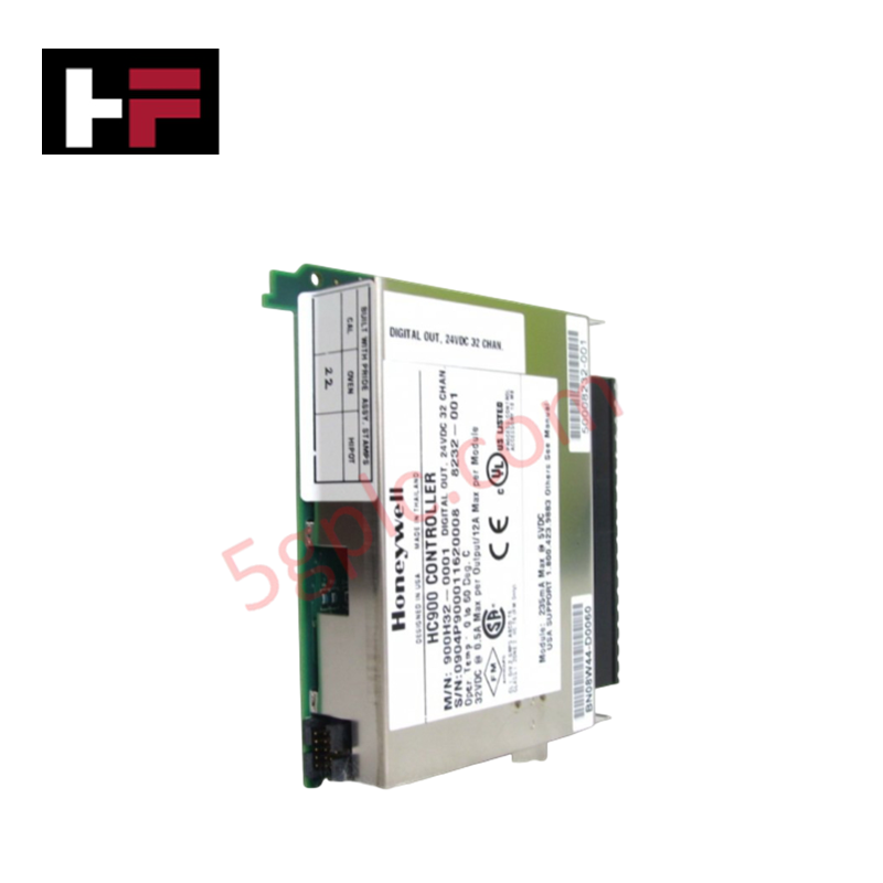
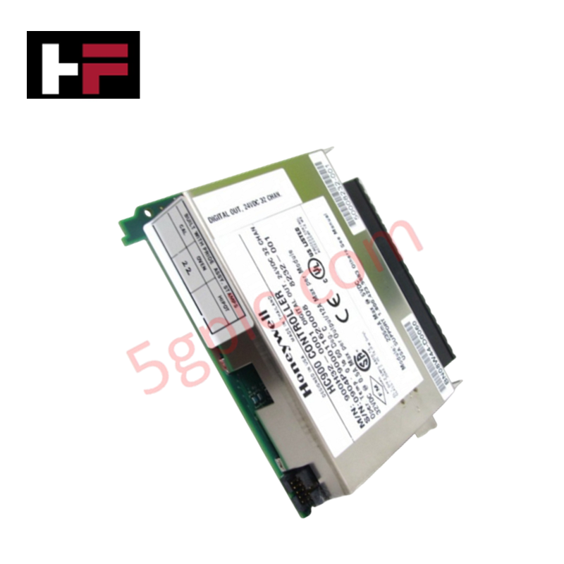
Configured for discrete load actuation and field device switching in Honeywell IPC 620 rack platforms, the Honeywell 621-6501 (621-6501 Digital Output Module) provides direct physical/electrical execution. It handles sourcing transistor switching for up to 8 discrete 24 VDC channels, executing PLC output logic states directly to field actuators.
Hardware Specifications
| Parameter | Specification |
|---|---|
| Model | 621-6501 |
| Brand | Honeywell |
| Origin | USA |
| Weight | 0.6 kg |
| Dimensions | 3.0 cm x 24.1 cm x 17.3 cm (1.2 in x 9.5 in x 6.8 in) |
| Operating Temp | 0 deg C to 60 deg C |
| Power Consumption | 110 mA max (+5 VDC backplane) |
| Output Type | 24 VDC Sourcing Transistor |
| Output Channels | 8 Channels |
| Operating Voltage Range | 11-28 VDC |
| Maximum Output Current | 2 A per channel, 6 A per common, 8 A per module |
| Surge Current | 5 A for 10 ms (non-repetitive) |
| Off-State Leakage | Less than or equal to 5 mA |
| On-State Voltage Drop | Less than or equal to 2 VDC at 2 A load |
| Circuit Fusing | 1 x 3 A Fast-Blow Fuse per channel |
| Compatible Chassis | Honeywell IPC 620 Chassis |
Channel-to-Channel Isolation and Output Protection
The Honeywell 621-6501 output stage incorporates galvanically isolated channel grouping to prevent field-side voltage transients from damaging backplane processing logic. Each of the 8 sourcing channels contains an independent 3 A fast-blow fuse to clear overcurrent fault conditions before thermal breakdown occurs in the output transistors. The module architecture maintains channel-to-channel isolation between distinct output groups, suppressing inductive switching noise during inductive load de-energization across field loops.
Frequently Asked Questions
Q: What is the procedure if an individual channel output fuse opens?
A: De-energize field power to the module, remove the module from the rack chassis, and replace the blown channel fuse with a rated 3 A fast-blow fuse before restoring power.
Q: Can output channels be wired in parallel to increase continuous current capability above 2 A?
A: Paralleling outputs on the same module is not recommended due to minor variations in transistor turn-on timing, which can cause transient current imbalances exceeding single-channel limits.
Field Installation Guidelines
- Turn off backplane rack power and external 24 VDC field supplies prior to inserting the module into the IPC 620 chassis.
- Align the printed circuit board with the chassis card guides and slide the module inward until the rear backplane connector locks securely.
- Tighten top and bottom panel mounting screws to establish chassis frame electrical bonding.
- Route field output wiring in separate conduit pathways from low-level analog or communication cables.
- Verify fuse integrity and correct 24 VDC power supply polarity at the field terminal block prior to energizing field loads.
Additional Information
- 100% Genuine Parts: All products are original and authentic, ensuring reliable industrial performance.
- 30-Day Refund Guarantee: Return any in-stock item within 30 days in original, unopened packaging for a full refund (excluding shipping and fees).
- 12-Month Warranty: Covers defects in materials or workmanship; excludes misuse, normal wear, or unauthorized modifications.
- Worldwide Shipping: We ship via USPS, UPS, FedEx, and DHL. Delivery times vary by country and may be subject to customs or import fees.
- Support & Contact: Technical and warranty assistance is available anytime. Contact us here: Contact.
- Purchase Guidance: Check product specifications and compatibility carefully before ordering to ensure proper application.
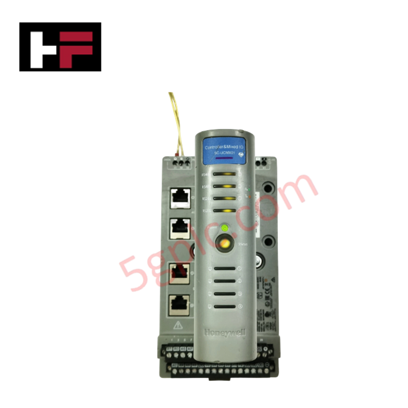
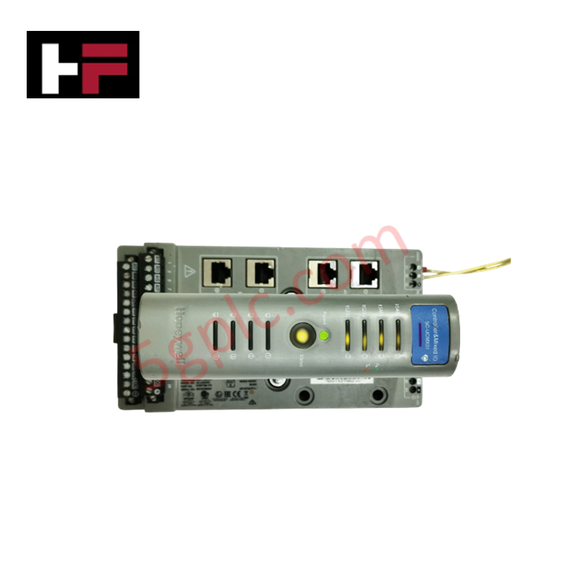
Tech & Buying Guide

Transforming Shop Floor Data into Actionable Insights: A Deep Dive into MES
Manufacturing Execution Systems serve as the digital backbone of modern factory floors. Positioned at Level 3 of the ISA-95 automation pyramid, MES links enterprise resource planning with real-time shop floor control systems. Today, industrial operators rely on MES software to bridge operational strategy with physical production execution.

Managed Switch vs. Unmanaged Switch: Industrial Ethernet Architecture

Hot Standby vs. Cold Standby Redundancy in Industrial Automation
System availability determines process safety and productivity in industrial automation. Control engineers deploy redundancy to eliminate single points of failure. This technical guide evaluates Hot Standby vs. Cold Standby architectures, comparing failover speeds, memory sync, cost trade-offs, and field selection criteria.