












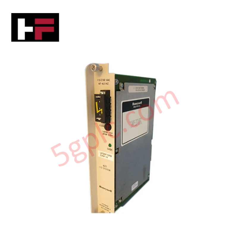
Product Details
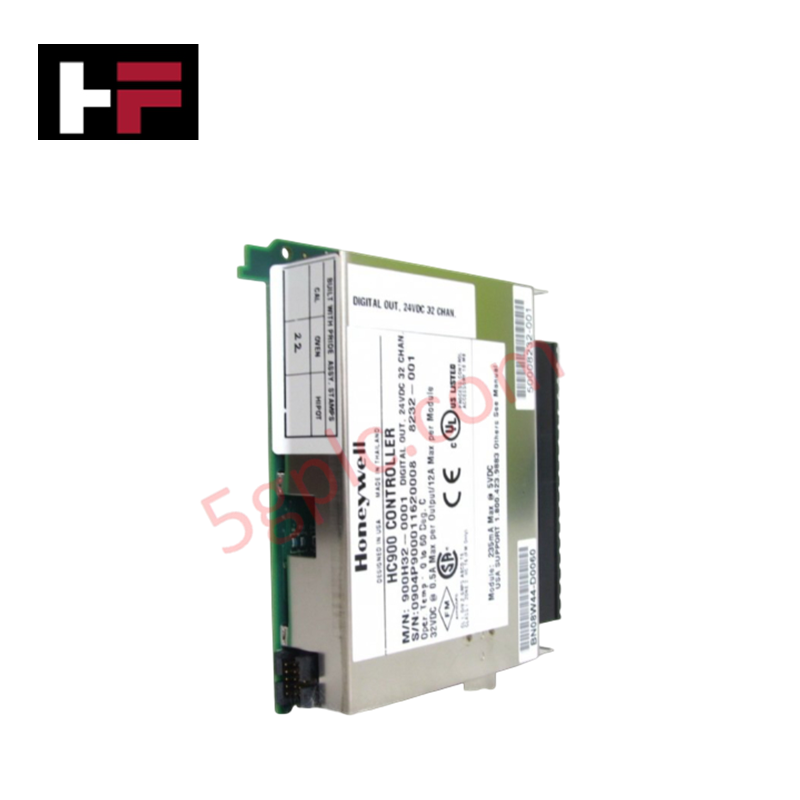
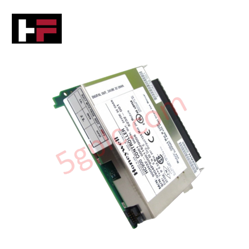
Configured for discrete load switching in IPC 620 and TDC control platforms, the Honeywell 621-2200R (621-2200R Output Module) provides direct electrical execution for sixteen AC output channels. The module functions as a hardware interface to drive field actuators, solenoids, and contactors, managing the transition of AC voltage states based on logic commands received from the system backplane.
Hardware Specifications
| Parameter | Specification |
|---|---|
| Model | 621-2200R |
| Brand | Honeywell |
| Weight | 0.55 kg |
| Dimensions | 120 x 80 x 50 mm |
| Channels | 16 AC output points |
| Signal Type | 120 / 240 VAC |
| Mounting | Rack-mounted PCB |
Channel-to-Channel Isolation and Loop Integrity
The 621-2200R incorporates signal isolation to decouple the high-voltage AC field environment from the low-voltage logic circuitry. This architectural approach is intended to mitigate the effects of line-side transients and voltage surges common in legacy AC distribution networks. Maintaining consistent load current within the rated threshold of the output stages is required to prevent localized heating and ensure the longevity of the relay or triac switching components.
Frequently Asked Questions
Q: Does the 621-2200R support mixed-voltage load configurations on a single module?
A: Users must adhere to system documentation regarding common return paths. Mixing AC voltage potentials across channels requires strict electrical separation and verification that the module's isolation barriers are not exceeded.
Q: Is this module compatible with inductive loads without additional suppression?
A: No. Inductive loads such as solenoids or contactor coils generate back-EMF upon de-energization. External RC snubbers or MOVs must be installed across the load to protect the module's output switching elements from excessive voltage spikes.
Field Installation Guidelines
- System De-energization: Before inserting or removing the module from the rack, ensure all power to the backplane and field-side AC circuits is fully isolated.
- Backplane Engagement: Align the module carefully with the rack guide rails. Ensure the edge connector is fully seated to prevent intermittent contact or bus communication failures.
- Wiring and Shielding: Utilize standard industrial AC cabling. Ensure that high-voltage output conductors are physically segregated from low-voltage signal cables to minimize inductive interference.
- Torque and Termination: Verify that all field wires are securely terminated to the screw terminals. Loose connections under AC load conditions are a primary cause of contact oxidation and thermal failure.
Additional Information
- 100% Genuine Parts: All products are original and authentic, ensuring reliable industrial performance.
- 30-Day Refund Guarantee: Return any in-stock item within 30 days in original, unopened packaging for a full refund (excluding shipping and fees).
- 12-Month Warranty: Covers defects in materials or workmanship; excludes misuse, normal wear, or unauthorized modifications.
- Worldwide Shipping: We ship via USPS, UPS, FedEx, and DHL. Delivery times vary by country and may be subject to customs or import fees.
- Support & Contact: Technical and warranty assistance is available anytime. Contact us here: Contact.
- Purchase Guidance: Check product specifications and compatibility carefully before ordering to ensure proper application.
Tech & Buying Guide

Transforming Shop Floor Data into Actionable Insights: A Deep Dive into MES
Manufacturing Execution Systems serve as the digital backbone of modern factory floors. Positioned at Level 3 of the ISA-95 automation pyramid, MES links enterprise resource planning with real-time shop floor control systems. Today, industrial operators rely on MES software to bridge operational strategy with physical production execution.

Managed Switch vs. Unmanaged Switch: Industrial Ethernet Architecture

Hot Standby vs. Cold Standby Redundancy in Industrial Automation
System availability determines process safety and productivity in industrial automation. Control engineers deploy redundancy to eliminate single points of failure. This technical guide evaluates Hot Standby vs. Cold Standby architectures, comparing failover speeds, memory sync, cost trade-offs, and field selection criteria.