










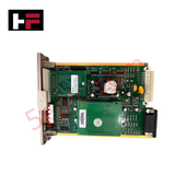
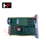
Product Details
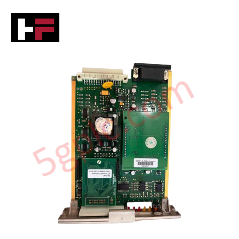
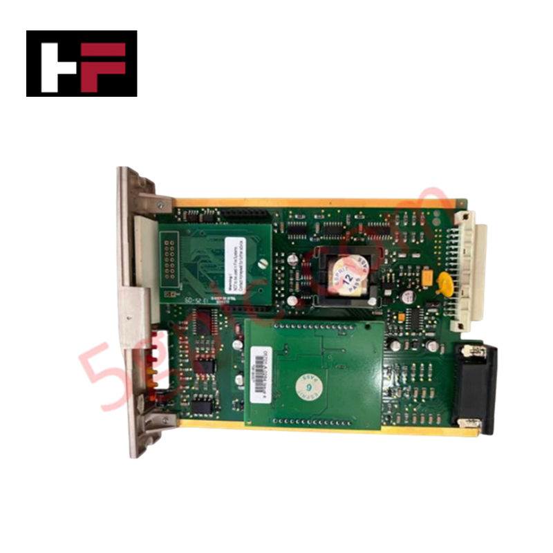
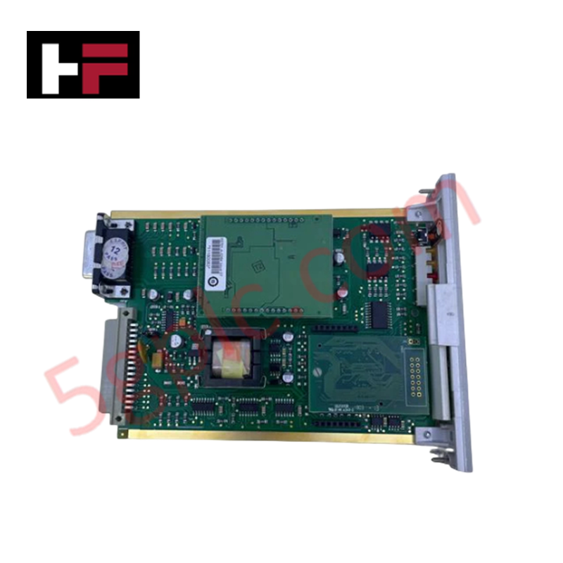
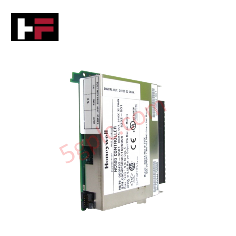
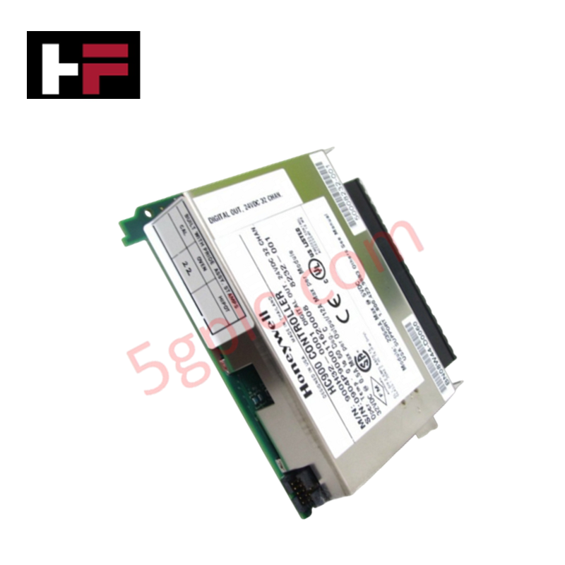
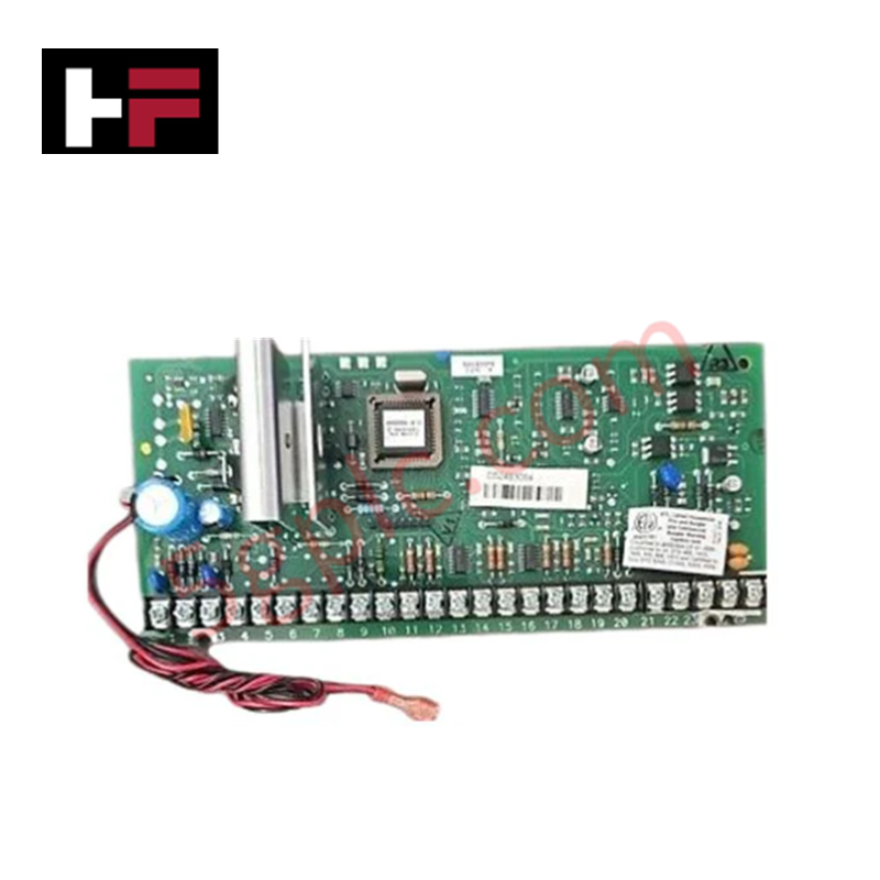
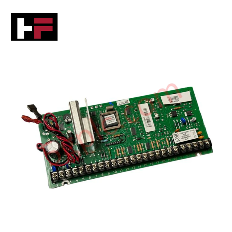
Configured for catalytic sensor excitation in Zellweger System 57 gas detection controllers, the Honeywell 05701-A-0284 (05701-A-0284 Sensor Drive Module) provides direct physical/electrical execution of sensor drive current and signal conditioning. The module maintains the necessary excitation parameters for catalytic sensing elements, ensuring valid concentration data transmission to the host controller within the System 57 platform.
Hardware Specifications
| Parameter | Specification |
|---|---|
| Model | 05701-A-0284 |
| Brand | Honeywell |
| Origin | USA |
| Weight | 1.2 kg |
| Dimensions | 200 mm x 100 mm x 50 mm |
| Operating Temp | -20 to 50 deg C |
| Power Consumption | 24 V DC |
| Sensor Type | Catalytic |
Channel-to-Channel Isolation
The 05701-A-0284 module employs channel-to-channel isolation architecture to protect the sensor signal path from common-mode voltage interference and ground potential shifts within the System 57 rack. This electrical separation is mandatory to maintain the sensitivity of the catalytic sensor and to ensure that signals are correctly processed by the 4-20 mA loop protocol without interference from adjacent control cards. Isolation barriers also function to prevent cross-talk between sensor loops, ensuring that detection threshold triggers are accurately mapped to the specific channel under surveillance.
Frequently Asked Questions
Q: Can the 05701-A-0284 be hot-swapped while the System 57 backplane is powered?
A: No. Any attempt to remove or install this module while the chassis is energized may induce electrical transients or damage the connector pins. The system must be de-energized prior to module handling.
Q: How is the excitation current verified after installation?
A: Post-installation, the excitation current must be checked via the central control unit's diagnostic interface to ensure it matches the specific requirements of the connected catalytic sensor.
Field Installation Guidelines
- Physical Mounting: Insert the module into the designated System 57 chassis slot. Align the module carefully with the rear connector to avoid pin damage. Secure the module using the built-in locking mechanism.
- Shielding and Grounding: Use shielded twisted-pair cabling for all sensor inputs. The shield must be connected to a clean earth ground at the cabinet entry to minimize the influence of electromagnetic noise on the catalytic bridge circuit.
- Wiring Separation: Route sensor inputs away from high-power AC lines, motor drives, and relay output cabling. Maintain a minimum separation of 150 mm to avoid induced signal fluctuations.
- Cable Termination: Ensure all terminals are tightened to the specified torque range. Poor electrical contact at the terminal block can lead to resistance variations in the catalytic bridge, resulting in sensor drift or false alarm states.
Additional Information
- 100% Genuine Parts: All products are original and authentic, ensuring reliable industrial performance.
- 30-Day Refund Guarantee: Return any in-stock item within 30 days in original, unopened packaging for a full refund (excluding shipping and fees).
- 12-Month Warranty: Covers defects in materials or workmanship; excludes misuse, normal wear, or unauthorized modifications.
- Worldwide Shipping: We ship via USPS, UPS, FedEx, and DHL. Delivery times vary by country and may be subject to customs or import fees.
- Support & Contact: Technical and warranty assistance is available anytime. Contact us here: Contact.
- Purchase Guidance: Check product specifications and compatibility carefully before ordering to ensure proper application.
Tech & Buying Guide

Transforming Shop Floor Data into Actionable Insights: A Deep Dive into MES
Manufacturing Execution Systems serve as the digital backbone of modern factory floors. Positioned at Level 3 of the ISA-95 automation pyramid, MES links enterprise resource planning with real-time shop floor control systems. Today, industrial operators rely on MES software to bridge operational strategy with physical production execution.

Managed Switch vs. Unmanaged Switch: Industrial Ethernet Architecture

Hot Standby vs. Cold Standby Redundancy in Industrial Automation
System availability determines process safety and productivity in industrial automation. Control engineers deploy redundancy to eliminate single points of failure. This technical guide evaluates Hot Standby vs. Cold Standby architectures, comparing failover speeds, memory sync, cost trade-offs, and field selection criteria.