










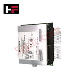
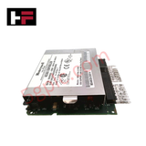
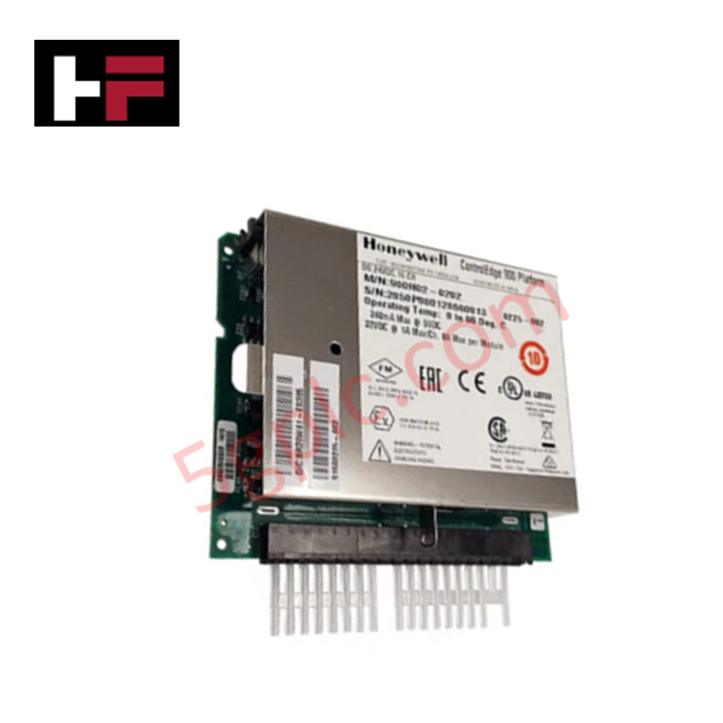
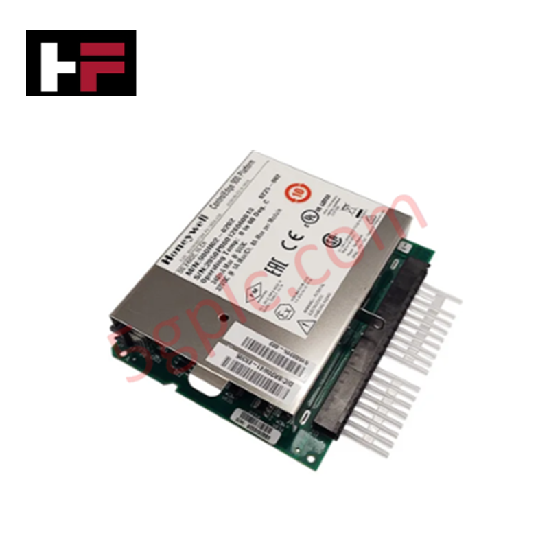
Product Details
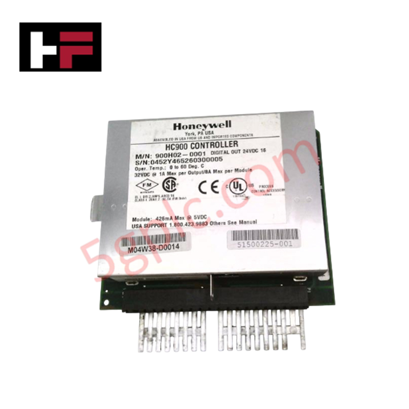
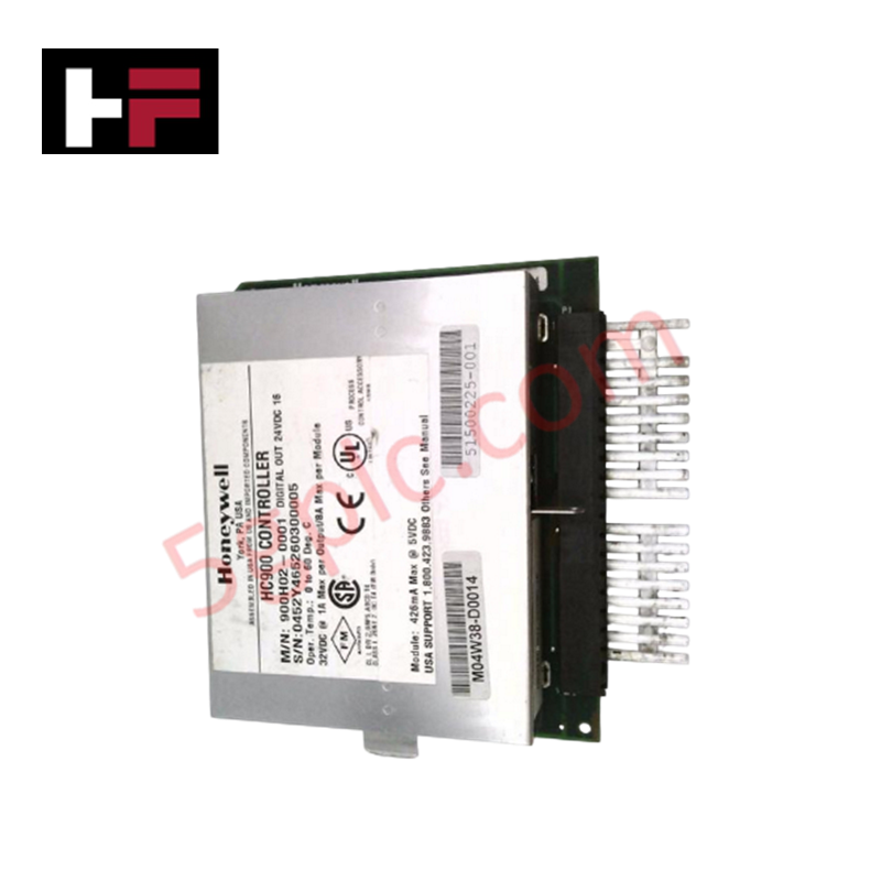
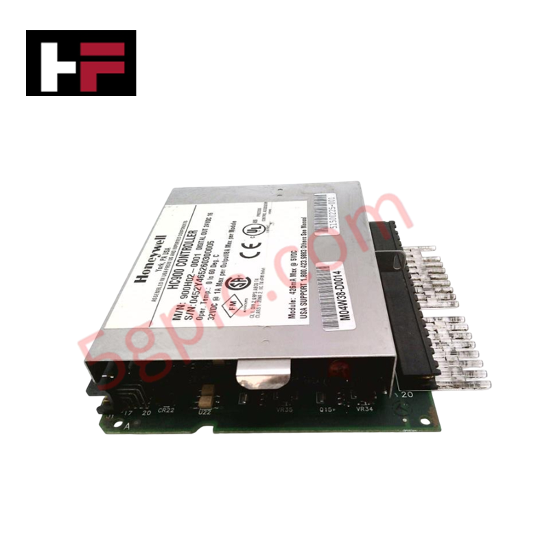
Configured for high-density discrete signal switching in HC900 control networks, the Honeywell 900H02-0001 (900H02 Digital Output Module) provides direct physical/electrical execution. The module manages external 24 VDC to 32 VDC loads via solid-state switching channels based on internal processor states.
Hardware Specifications
| Parameter | Specification |
|---|---|
| Model | 900H02-0001 |
| Brand | Honeywell |
| Series / Module Type | HC900 / Digital Output Module |
| Origin | USA |
| Weight | 0.35 lbs (0.16 kg) |
| Dimensions | Standard HC900 chassis slot allocation |
| Operating Temp | 0 to 60 deg C |
| Power Consumption | 426 mA maximum at 5 VDC internal backplane draw |
| Output Channels | 16 discrete outputs |
| Maximum Voltage Range | 32 VDC |
| Maximum Current Rating | 1 A per channel / 8 A maximum per module |
Channel-to-Channel Isolation and Loop Integrity
The electrical design of the 900H02-0001 features rigorous galvanic channel-to-channel isolation zones alongside optical barrier separation between the internal logic circuitry and the 32 VDC field side routing. This physical configuration prevents common-mode noise propagation and ground loop currents from injecting electrical anomalies into neighboring 4-20 mA HART loop protocol lines or low-voltage analog inputs positioned on the same rack backplane. Inductive transient suppression networks are paired with the switching elements to filter out high-voltage feedback spikes from collapsing magnetic fields in solenoid coils.
Frequently Asked Questions
Q: Does the 900H02-0001 module support live hot-swap insertion and extraction during active rack processing?
A: No. Removing or inserting the module while the HC900 backplane is energized can induce transient electrical noise on the shared bus, causing internal communication faults or unsafe dropouts on adjacent channels.
Q: What are the backplane current load limitations when deploying multiple 900H02-0001 modules in a single rack assembly?
A: Each module pulls a maximum of 426 mA from the 5 VDC logic supply. Total rack consumption must be calculated against the rating of the primary power supply module to prevent overcurrent trip conditions.
Field Installation Guidelines
- Chassis Slot Seating: Align the module circuit board with the upper and lower plastic guides within the designated slot. Push the assembly straight into the backplane until the interface pins lock securely.
- Field Wiring Routing Constraints: Separate all VDC discrete output loops from high-voltage alternate current paths and variable frequency drive motor leads within the containment trays to prevent cross-talk coupling.
- External Fuse Allocation: Install high-speed current limiting fuses on the field supply side for each block of channels to prevent continuous module overloads from breaching the 8 A absolute physical limit.
- Shield and Ground Continuity: Terminate external cable drain wires and internal reference ground paths at the unified enclosure grounding bar before energizing the module input channels.
Additional Information
- 100% Genuine Parts: All products are original and authentic, ensuring reliable industrial performance.
- 30-Day Refund Guarantee: Return any in-stock item within 30 days in original, unopened packaging for a full refund (excluding shipping and fees).
- 12-Month Warranty: Covers defects in materials or workmanship; excludes misuse, normal wear, or unauthorized modifications.
- Worldwide Shipping: We ship via USPS, UPS, FedEx, and DHL. Delivery times vary by country and may be subject to customs or import fees.
- Support & Contact: Technical and warranty assistance is available anytime. Contact us here: Contact.
- Purchase Guidance: Check product specifications and compatibility carefully before ordering to ensure proper application.






Tech & Buying Guide

Understanding VFD Mechanical Brake Logic and Control in Industrial Automation
Variable Frequency Drives (VFDs) play a crucial role in modern industrial automation by controlling motor speed, torque, and acceleration. However, high-inertia loads and vertical lifting systems require precise mechanical braking logic to ensure operational safety and prevent equipment damage.

Why Programmable Logic Controllers Drop into Stop Mode: An Expert Analysis
Industrial automation systems rely heavily on Programmable Logic Controllers (PLCs) to maintain uninterrupted production. When a PLC unexpectedly shifts from Run to Stop mode, whole manufacturing lines stall.
As control systems evolve across modern factory automation, understanding the root causes of these interruptions helps engineers minimize costly downtime. This technical guide breaks down why PLCs trip into Stop mode and provides practical strategies to mitigate system faults.

Understanding Root Causes of Unplanned PLC Stop Mode in Industrial Automation
Modern Programmable Logic Controllers manage execution through distinct operational states: Run, Stop, Start-Up, and Hold. During power-up, a controller initializes memory registers within Stop mode before briefly transitioning to Start-Up mode. During this phase, internal self-diagnostics evaluate system integrity across hardware and user programs. If the controller detects no critical faults, it enters Run mode to execute the control program continuously. However, any severe system anomaly forces the CPU back into Stop mode immediately to prevent erratic machine behavior across the plant floor.