










Product Details
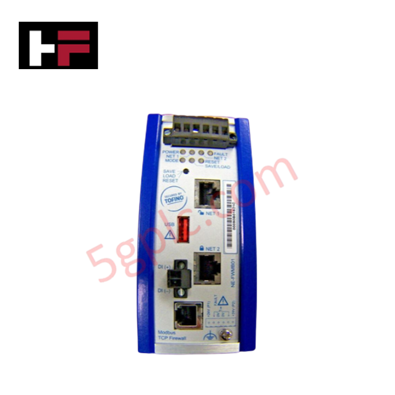
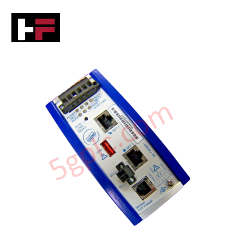
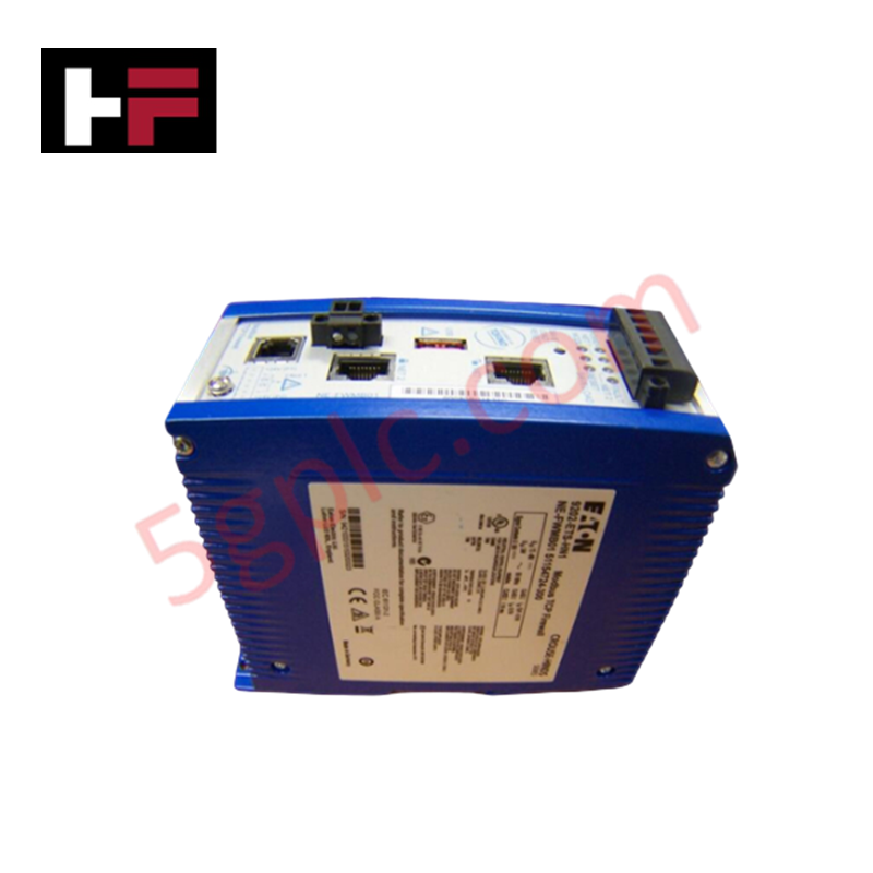
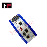
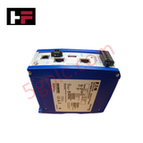
The Honeywell NE-FWMB01, also cataloged as the NE-FWMB01 Modbus Firewall Module, operates as a dedicated hardware component for industrial Modbus communication filtering and network isolation within Honeywell Experion PKS platforms.
Hardware Specifications
| Parameter | Specification |
|---|---|
| Model | NE-FWMB01 |
| Brand | Honeywell |
| Origin | USA |
| Operating Temp | -40 to +70 deg C |
| Power Consumption | < 170 mA typ, < 350 mA max at 24 VDC |
| Operating Voltage | 24 VDC nominal (9 VDC to 32 VDC) |
| Power Inputs | Dual redundant inputs |
| Power Fail Inputs | Two inputs |
| Terminal Connections | Screw cage-clamp 24...12 AWG (0.2...2.5 mm2) |
| Indicators | Power, Fault, Event, Mode, Link Activity and Speed |
| Configuration | USB storage load/save via Config Switch |
4-20 mA HART Loop Protocol & Channel Isolation
The Modbus firewall hardware enforces deterministic data packet inspection across serial and Ethernet communication channels, shielding DCS controller racks from unverified network traffic. Internal galvanic power isolation and signal filtering prevent ground loop currents from propagating across serial field loops. This electrical segregation protects sensitive analog processing circuits, maintaining 4-20 mA HART loop protocol signal integrity and preventing common-mode noise corruption on interconnected analog I/O channels.
Frequently Asked Questions
Q: How is offline configuration applied to the NE-FWMB01 module?
A: Configurations can be loaded directly from USB storage media using the hardware Config Switch without requiring an active network setup connection.
Q: What power redundancy features are integrated into the NE-FWMB01 hardware?
A: The module includes dual redundant 24 VDC nominal power inputs (operating range 9 VDC to 32 VDC) along with two dedicated Power Fail Inputs.
Q: What is the operating temperature range for field installation?
A: The module is specified for operation in ambient temperatures ranging from -40 deg C to +70 deg C.
Field Installation Guidelines
- Mount the module securely onto the cabinet DIN-rail or rack frame before attaching power and signal connections.
- Wire dual 24 VDC primary and backup power feeds into the screw cage-clamp terminals using 24...12 AWG conductors.
- Terminate signal cable shielding to the main panel earth ground bus to minimize high-frequency noise ingress.
- Verify all LED indicators (Power, Fault, Event, Mode) during initial power-up to confirm valid module status before enabling bus traffic.
- Maintain required physical clearance around thermal vents to ensure passive cooling performance within enclosure limits.
Additional Information
- 100% Genuine Parts: All products are original and authentic, ensuring reliable industrial performance.
- 30-Day Refund Guarantee: Return any in-stock item within 30 days in original, unopened packaging for a full refund (excluding shipping and fees).
- 12-Month Warranty: Covers defects in materials or workmanship; excludes misuse, normal wear, or unauthorized modifications.
- Worldwide Shipping: We ship via USPS, UPS, FedEx, and DHL. Delivery times vary by country and may be subject to customs or import fees.
- Support & Contact: Technical and warranty assistance is available anytime. Contact us here: Contact.
- Purchase Guidance: Check product specifications and compatibility carefully before ordering to ensure proper application.


Tech & Buying Guide

Understanding VFD Mechanical Brake Logic and Control in Industrial Automation
Variable Frequency Drives (VFDs) play a crucial role in modern industrial automation by controlling motor speed, torque, and acceleration. However, high-inertia loads and vertical lifting systems require precise mechanical braking logic to ensure operational safety and prevent equipment damage.

Why Programmable Logic Controllers Drop into Stop Mode: An Expert Analysis
Industrial automation systems rely heavily on Programmable Logic Controllers (PLCs) to maintain uninterrupted production. When a PLC unexpectedly shifts from Run to Stop mode, whole manufacturing lines stall.
As control systems evolve across modern factory automation, understanding the root causes of these interruptions helps engineers minimize costly downtime. This technical guide breaks down why PLCs trip into Stop mode and provides practical strategies to mitigate system faults.

Understanding Root Causes of Unplanned PLC Stop Mode in Industrial Automation
Modern Programmable Logic Controllers manage execution through distinct operational states: Run, Stop, Start-Up, and Hold. During power-up, a controller initializes memory registers within Stop mode before briefly transitioning to Start-Up mode. During this phase, internal self-diagnostics evaluate system integrity across hardware and user programs. If the controller detects no critical faults, it enters Run mode to execute the control program continuously. However, any severe system anomaly forces the CPU back into Stop mode immediately to prevent erratic machine behavior across the plant floor.