











Product Details
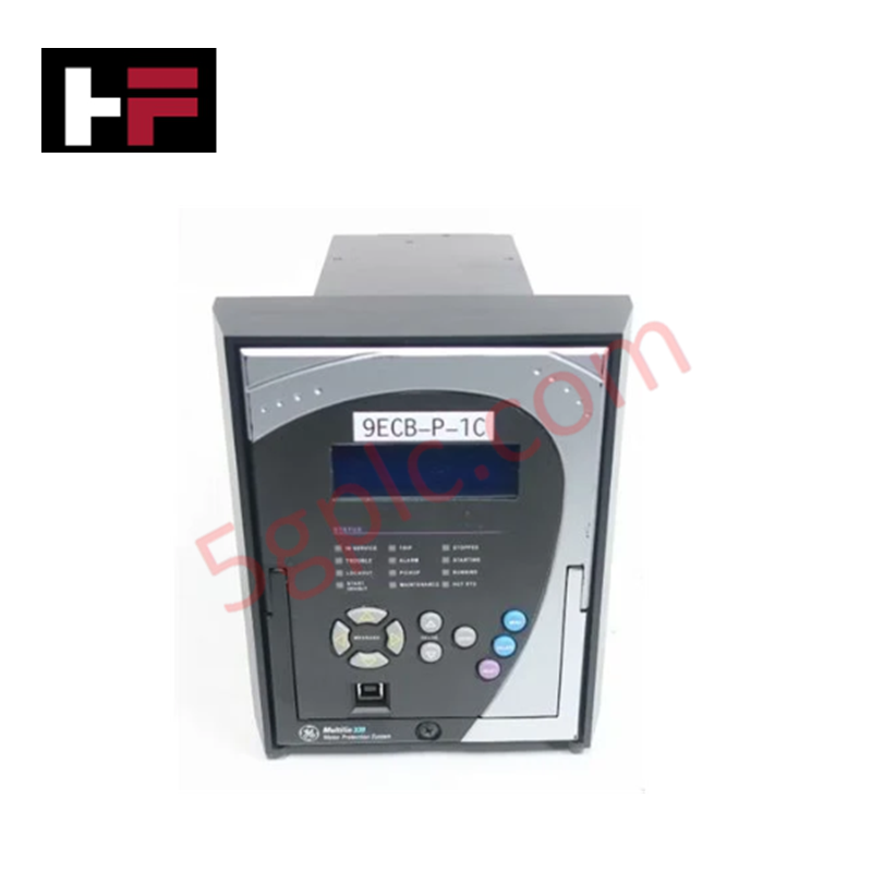
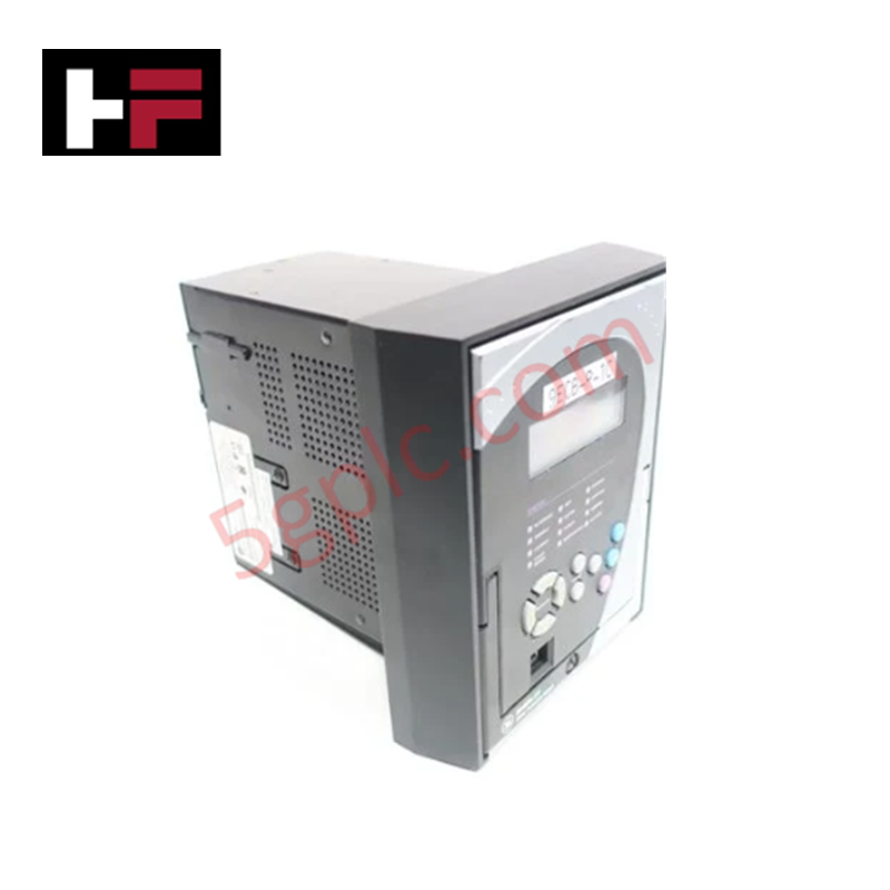
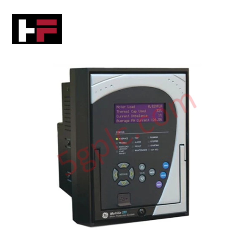
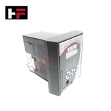
Configured for current monitoring, thermal overload management, and fault detection in 339 Motor Protection System networks, the GE 339-E-P1-G1-H-E-S-N-P-3E-D-N (GE 339 Motor Protection Relay) provides direct physical/electrical execution.
Suffix Breakdown & Model Matrix
The alphanumeric hardware catalog code 339-E-P1-G1-H-E-S-N-P-3E-D-N specifies exact hardware options and electrical configurations:
- 339: 339 Motor Protection System series base hardware.
- E: English display interface configuration without programmable LEDs.
- P1: 1 A three-phase current inputs.
- G1: 1 A ground current input.
- H: Universal high-voltage power supply (110 to 250 VDC / 110 to 230 VAC).
- E: I/O expansion board with 10 contact inputs and 7 contact outputs (2 Form A, 5 Form C).
- S: Standard current protection suite (37, 46, 48, 49, 50P, 50G/SG, 50N, 50L, 51R, 66, 86, 51N, 51P, 50BF).
- N: No additional selection option.
- P: Standard platform functionality.
- 3E: Advanced Ethernet interface (Copper + MTRJ Fiber) supporting Modbus TCP/IP, DNP3.0, IEC 60870-5-104, and IEC 61850.
- D: Protection relay encased in drawout chassis housing.
- N: Standard harsh environment coating option (None).
Hardware Specifications
| Parameter | Specification |
|---|---|
| Model | 339-E-P1-G1-H-E-S-N-P-3E-D-N |
| Brand | GE Multilin |
| Origin | USA |
| Weight | 5.0 kg |
| Dimensions | 177 x 218 x 205 mm |
| Operating Temp | -40 to 60 deg C |
| Power Consumption | 15 W |
| System Series | 339 Motor Protection System |
| Power Supply | 110 to 250 VDC / 110 to 230 VAC |
| Current Inputs | 1 A CT Phase (3-phase) / 1 A CT Ground |
| Contact Inputs/Outputs | 10 Contact Inputs / 7 Relay Outputs (2 Form A, 5 Form C) |
| Communication Ports | Ethernet Copper + Fiber (MTRJ) |
| Protocols | Modbus TCP/IP, DNP3.0, IEC 60870-5-104, IEC 61850 |
| Enclosure Style | Drawout design chassis |
Backplane Bus Communication Velocity and Firmware Flash Compatibility
The 339-E-P1-G1-H-E-S-N-P-3E-D-N features dual Ethernet hardware layers (copper and MTRJ optical fiber) to process high-speed protection commands across Substation Automation networks. High-speed internal bus architectures maintain high backplane bus communication velocity during real-time protective element evaluations (50P, 50G, 51P, 50BF). Microprocessor memory blocks maintain firmware flash compatibility across network protocol stacks, ensuring deterministic IEC 61580 GOOSE messaging latencies and Modbus TCP telemetry updates.
Frequently Asked Questions
Q: What current transformer secondary ratings are required for this model configuration?
A: This specific relay ordering code requires 1 A secondary phase current transformers (P1) and a 1 A secondary ground current transformer (G1).
Q: Can the drawout unit be safely extracted without disrupting external current loops?
A: Yes, the drawout chassis design (D) incorporates automatic CT shorting mechanisms that engage prior to internal terminal pin disconnection during drawout removal.
Q: Which network protocols are active on the 3E Ethernet communication option?
A: Option 3E enables Modbus TCP/IP, DNP3.0, IEC 60870-5-104, and IEC 61850 protocol stacks across both copper and MTRJ fiber Ethernet ports.
Field Installation Guidelines
Verify that auxiliary power sources (110 to 250 VDC / 110 to 230 VAC) are de-energized before inserting or wiring the drawout cradle assembly. Bond the dedicated earth grounding terminal on the back of the drawout case directly to the main cabinet earthing bus using heavy-gauge copper grounding braid. When connecting CT wiring to the rear terminals, ensure terminal screws are torqued to manufacturer specifications. Ensure all fiber optical MTRJ connectors remain covered with protective dust caps until final patch cable connection.
Additional Information
- 100% Genuine Parts: All products are original and authentic, ensuring reliable industrial performance.
- 30-Day Refund Guarantee: Return any in-stock item within 30 days in original, unopened packaging for a full refund (excluding shipping and fees).
- 12-Month Warranty: Covers defects in materials or workmanship; excludes misuse, normal wear, or unauthorized modifications.
- Worldwide Shipping: We ship via USPS, UPS, FedEx, and DHL. Delivery times vary by country and may be subject to customs or import fees.
- Support & Contact: Technical and warranty assistance is available anytime. Contact us here: Contact.
- Purchase Guidance: Check product specifications and compatibility carefully before ordering to ensure proper application.
Tech & Buying Guide

Demystifying the 5 Levels of Industrial Automation Architecture
Modern manufacturing relies on structured communication hierarchy to bridge physical shop-floor hardware with enterprise management software. This framework, commonly known as the Automation Pyramid, establishes how data flows between field devices, logic controllers, and corporate IT networks. Understanding these five distinct levels helps engineers and plant managers optimize system operations, reduce downtime, and implement seamless factory automation solutions.

Transforming Shop Floor Data into Actionable Insights: A Deep Dive into MES
Manufacturing Execution Systems serve as the digital backbone of modern factory floors. Positioned at Level 3 of the ISA-95 automation pyramid, MES links enterprise resource planning with real-time shop floor control systems. Today, industrial operators rely on MES software to bridge operational strategy with physical production execution.
