










Product Details
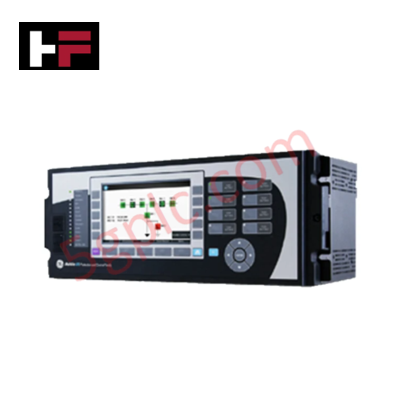
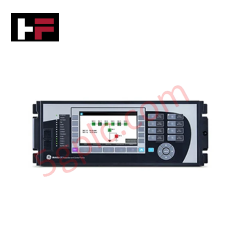
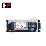
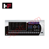
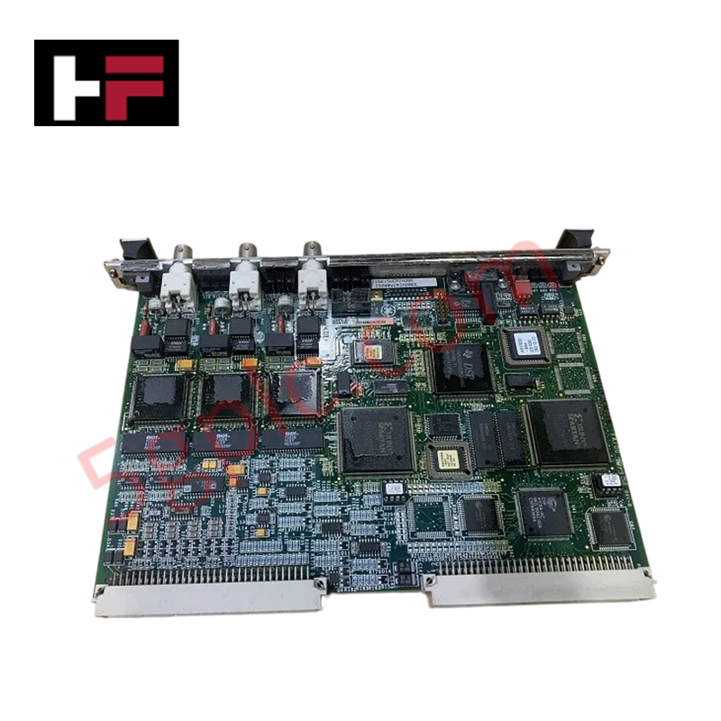
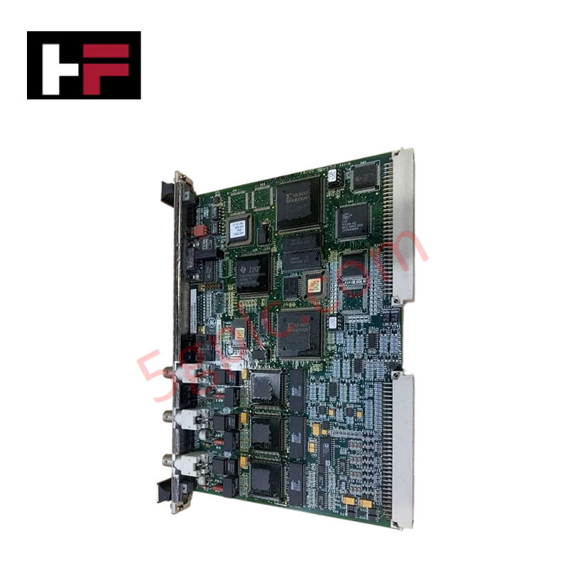
The GE T35A00HCHF8CH6UM8AP6CU8AW6C serves as the primary T35 Transformer Protection System utilized to execute high-speed transformer protective profiling and automated diagnostic routing across industrial electrical platforms. The hardware processes multi-channel analog inputs from three phase CTs, one ground CT, and four VTs to evaluate instantaneous differential algorithms. It manages localized automation through integrated digital, Form-A, and Form-C output relay matrices, establishing wide-area telemetry across an embedded 820 nm multimode LED communication link.
Hardware Specifications
| Parameter | Specification |
|---|---|
| Model | T35A00HCHF8CH6UM8AP6CU8AW6C |
| Brand | GE Multilin |
| Origin | Technical specifications determine factory origin |
| Weight | Physical rack mass varies by internal I/O option density |
| Dimensions | Standard 19-inch rack horizontal footprint |
| Operating Temp | -40 to +85 deg C |
| Power Consumption | Slot configuration and active relay load dependent |
| CPU Communication | RS485 & RS485 physical interfaces |
| Redundancy Protocol | Parallel Redundancy Protocol (PRP) enabled |
| Interface Panel | Vertical front panel with English text display |
| Current Inputs | Three 1 A / 5 A phase CTs + one 1 A / 5 A ground CT |
| Voltage Inputs | Four 120 V / 240 V VTs |
| Digital & Form-C I/O | 8 Form-C contact outputs plus associated inputs |
| Transducer & Form-A I/O | 6 Form-A (no monitoring) outputs + 4 digital inputs |
| Inter-Relay Comm | 820 nm, multimode, LED, 1 channel |
| Operating Voltages | 125 / 250 V AC/DC power supply |
| Contact Ratings | 24 VDC to 250 VAC switching operational limits / 10 A current |
Profinet / EtherNet/IP Deterministic Networks Integration
The modular processing backplane enforces internal bus separation rules to align current and voltage sampling waveforms under strict time constraints, ensuring absolute firmware flash compatibility across safety-interlocking execution states. Real-time protection calculation blocks run independently from serial background polling tasks, guaranteeing that high-density data distribution via the Parallel Redundancy Protocol (PRP) interface does not introduce latency or processing jitter to the primary sub-cycle transformer trip circuits.
Frequently Asked Questions
Q: Does this specific model architecture support live hot-swapping of the Form-C or Transducer I/O boards?
A: No. The internal processing backplane and structural pins are not designed for live module extraction. The 125 / 250 V AC/DC main supply line must be completely isolated from the system prior to pulling or installing card frames to avoid damage to internal logic tracks.
Q: How is data loss prevented over the inter-relay communication link if network interference occurs?
A: The 820 nm multimode fiber optic interface transmits data blocks directly via dedicated point-to-point physical links. Because this physical link is decoupled from the station serial bus, communication is immune to localized electromagnetic cross-talk and common-mode grid noise.
Field Installation Guidelines
- Chassis Grounding: Run a low-impedance copper conductor from the heavy-gauge grounding stud on the rear of the horizontal 19-inch rack frame directly to the master station panel earth bar.
- CT Circuit Isolation: Always short-circuit the secondary loops of the three phase CTs and single ground CT via external testing blocks prior to disconnecting any terminal blocks to avoid high-voltage transformer arcing.
- Fiber Optic Handling: Do not exceed the maximum allowable bend radius of the 820 nm multimode optical cable during routing inside the wireways to avoid signal attenuation or glass stress fractures.
Additional Information
- 100% Genuine Parts: All products are original and authentic, ensuring reliable industrial performance.
- 30-Day Refund Guarantee: Return any in-stock item within 30 days in original, unopened packaging for a full refund (excluding shipping and fees).
- 12-Month Warranty: Covers defects in materials or workmanship; excludes misuse, normal wear, or unauthorized modifications.
- Worldwide Shipping: We ship via USPS, UPS, FedEx, and DHL. Delivery times vary by country and may be subject to customs or import fees.
- Support & Contact: Technical and warranty assistance is available anytime. Contact us here: Contact.
- Purchase Guidance: Check product specifications and compatibility carefully before ordering to ensure proper application.
Tech & Buying Guide
Mitigating Emergency Stop Spurious Trips in Industrial Control Systems
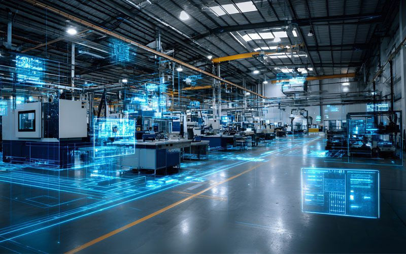
Emergency stop (E-Stop) pushbuttons serve as vital safety devices in factory automation and process control plants. Functional safety standards mandate normally-closed (NC) contact blocks to ensure fail-safe operation during wiring breaks or power outages. However, mechanical degradation over time can trigger unexpected spurious trips, halting production lines without an actual emergency. Understanding the underlying causes of mechanical contact failure allows automation engineers to implement robust, fault-tolerant safety circuits.
Redundant Automation Systems: Maximizing Uptime in Critical Control Applications
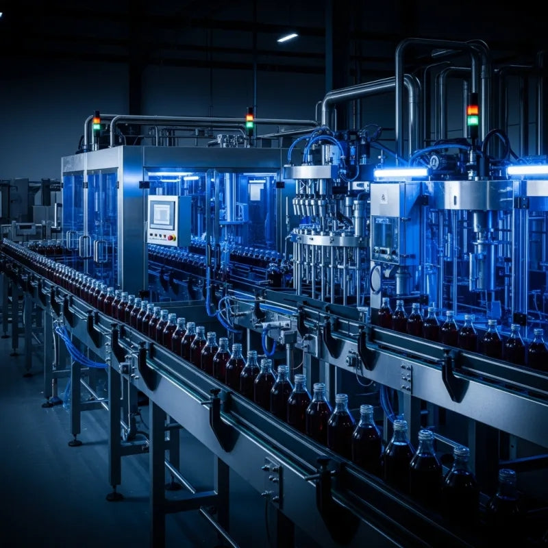
Industrial automation relies on continuous operational stability to prevent catastrophic downtime and financial loss. While standard dictionary definitions treat redundancy as superfluous, industrial engineers consider redundant control architectures indispensable for high-availability systems. Implementing backup hardware ensures seamless takeover during primary equipment failures, protecting critical infrastructure across manufacturing and process industries.
Demystifying the 5 Levels of Industrial Automation Architecture
Modern manufacturing relies on structured communication hierarchy to bridge physical shop-floor hardware with enterprise management software. This framework, commonly known as the Automation Pyramid, establishes how data flows between field devices, logic controllers, and corporate IT networks. Understanding these five distinct levels helps engineers and plant managers optimize system operations, reduce downtime, and implement seamless factory automation solutions.