










Product Details
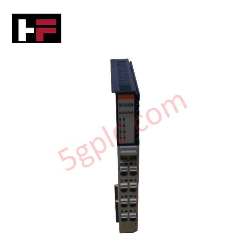
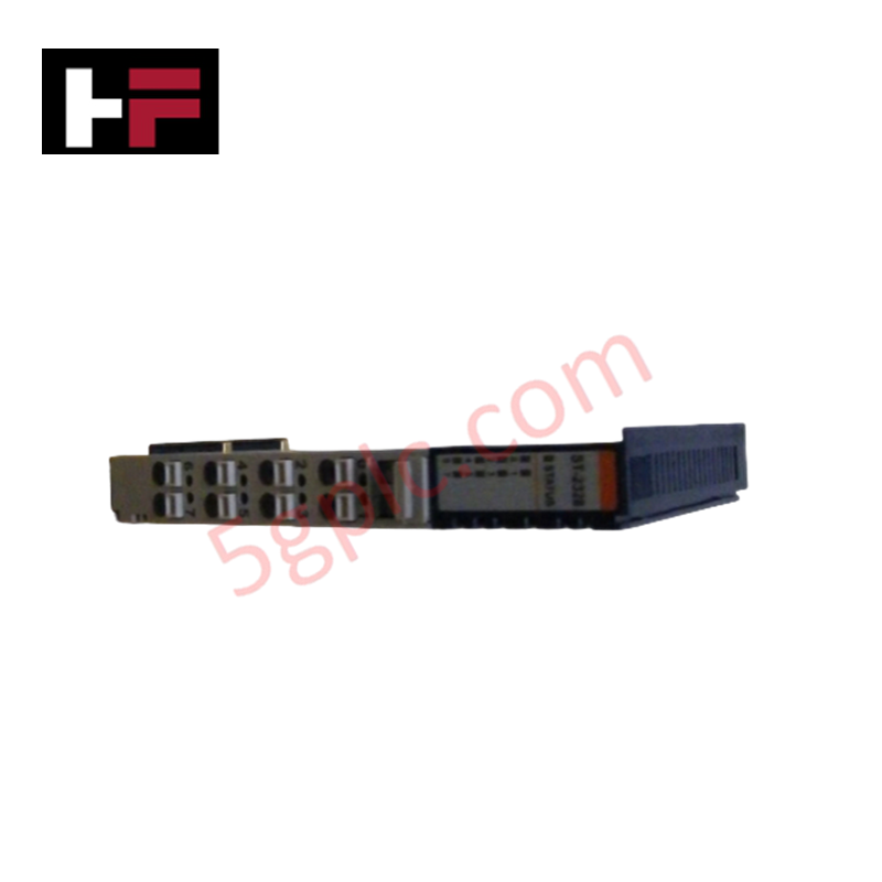
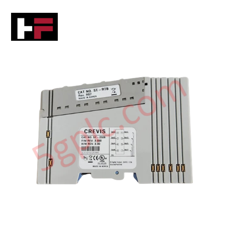
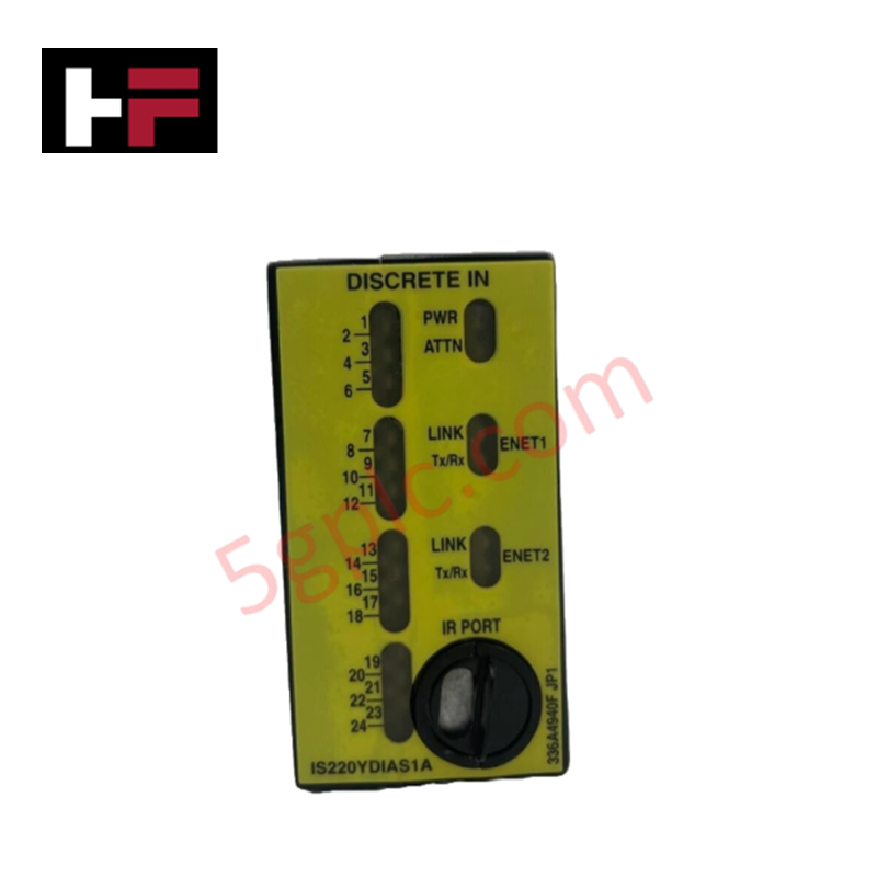
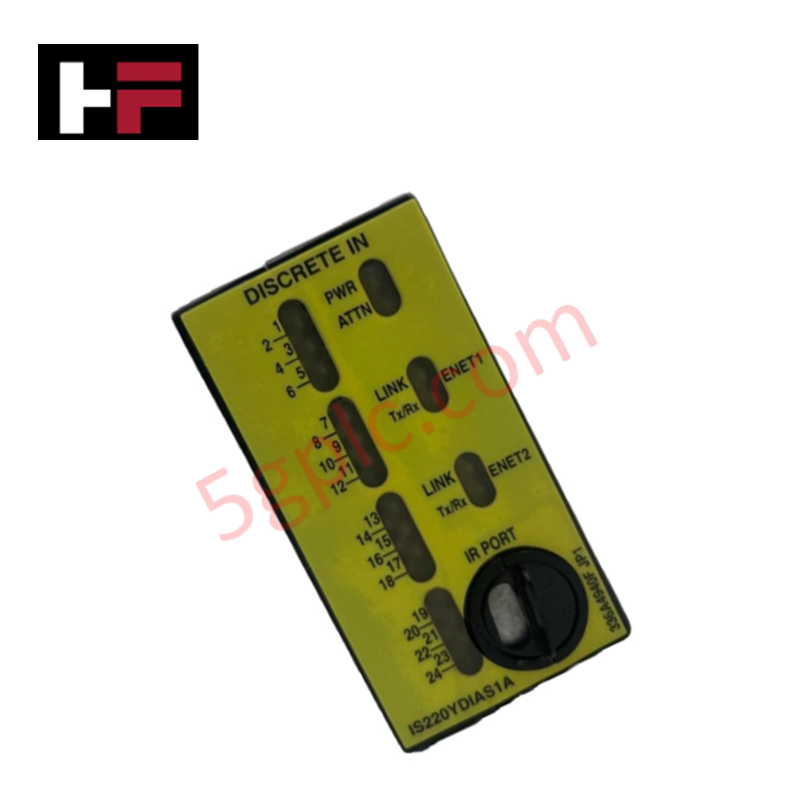
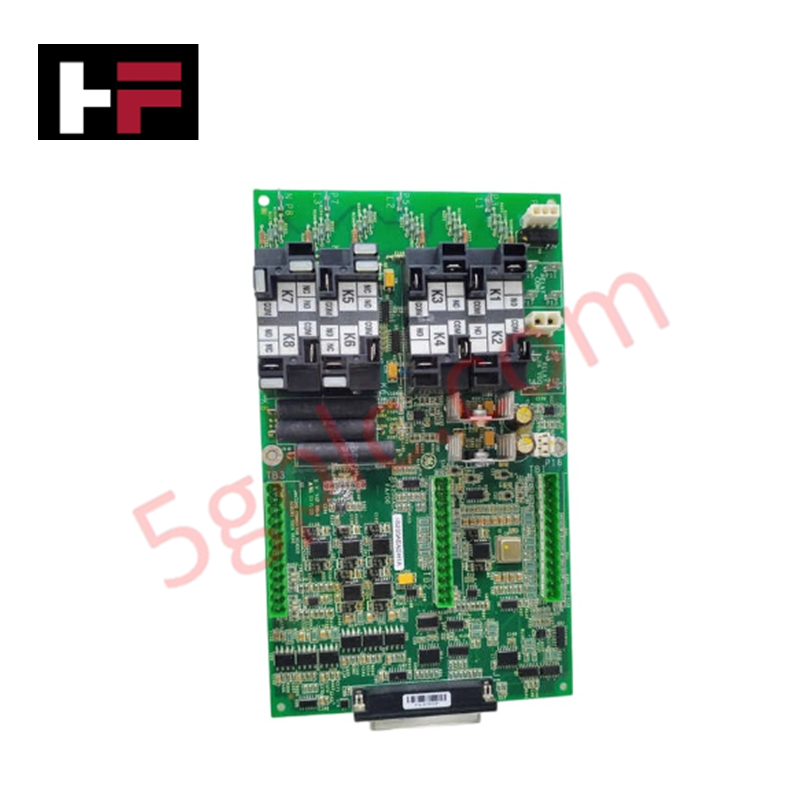
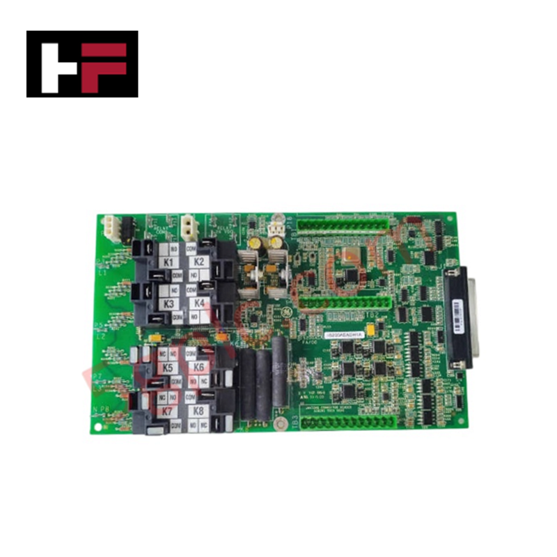
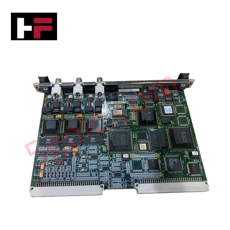
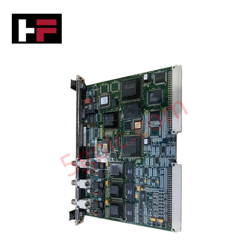
The GE ST-2328, also cataloged as the ST-2328 Digital Output Module, operates as a dedicated hardware component for discrete state actuation within RSTi Series network platforms.
Hardware Specifications
| Parameter | Specification |
|---|---|
| Model | ST-2328 |
| Brand | GE / GE Fanuc |
| Origin | United States |
| Weight | 0.05 kg |
| Dimensions | Standard RSTi Slice Form Factor |
| Operating Temp | 0 - 55 deg C |
| Power Consumption | Logic Rail Dependent |
| Output Points | 8 points |
| Output Logic | Positive logic (Source configuration) |
| Rated Voltage | 24 VDC |
| Output Current | 0.5 A per channel |
| Mounting | DIN-rail interface terminal base |
I/O Density Scaling and Deterministic Networks Integration
The module manages 8 discrete positive-logic output channels within a compact slice footprint to optimize I/O density scaling inside control enclosures. The internal circuitry drives external loads up to 0.5 A per point at a nominal 24 VDC rating. State data transfers from the master controller cross the network adapter over Profinet / EtherNet/IP deterministic networks, updating the local hardware image registers. Proper execution across the slice backplane depends directly on verifying firmware flash compatibility with the upstream bus coupler.
Frequently Asked Questions
Q: Does the ST-2328 module support live extraction or hot-swapping during active operation?
A: No. The parallel backplane connections on the RSTi platform do not possess staggered circuit layouts or pre-charge isolation layers. Removing the slice while the bus terminal base is energized will induce localized electrical faults and interrupt network data cycles.
Q: How is the positive logic structure reference wired on the field terminal side?
A: The sourcing channels supply 24 VDC directly from the internal power rail to the field load when activated. External field actuators must have their return lines terminated directly to the common negative DC reference rail of the supply circuit.
Field Installation Guidelines
- DIN-Rail Mounting Sequence: Align the module side interlocking guides with the adjacent RSTi unit. Press downward firmly onto the DIN rail until the integrated mechanical slide lock snaps completely into position.
- Conductor Separation Rules: Route the 24 VDC discrete output paths through isolated terminal wireways separated from alternating current (AC) distribution lines to prevent capacitive noise coupling.
- Common Power Distribution: Connect the auxiliary 24 VDC field power supply directly to the corresponding terminal base power distribution contacts to ensure the 0.5 A per channel drive limit is maintained under full load conditions.
Additional Information
- 100% Genuine Parts: All products are original and authentic, ensuring reliable industrial performance.
- 30-Day Refund Guarantee: Return any in-stock item within 30 days in original, unopened packaging for a full refund (excluding shipping and fees).
- 12-Month Warranty: Covers defects in materials or workmanship; excludes misuse, normal wear, or unauthorized modifications.
- Worldwide Shipping: We ship via USPS, UPS, FedEx, and DHL. Delivery times vary by country and may be subject to customs or import fees.
- Support & Contact: Technical and warranty assistance is available anytime. Contact us here: Contact.
- Purchase Guidance: Check product specifications and compatibility carefully before ordering to ensure proper application.
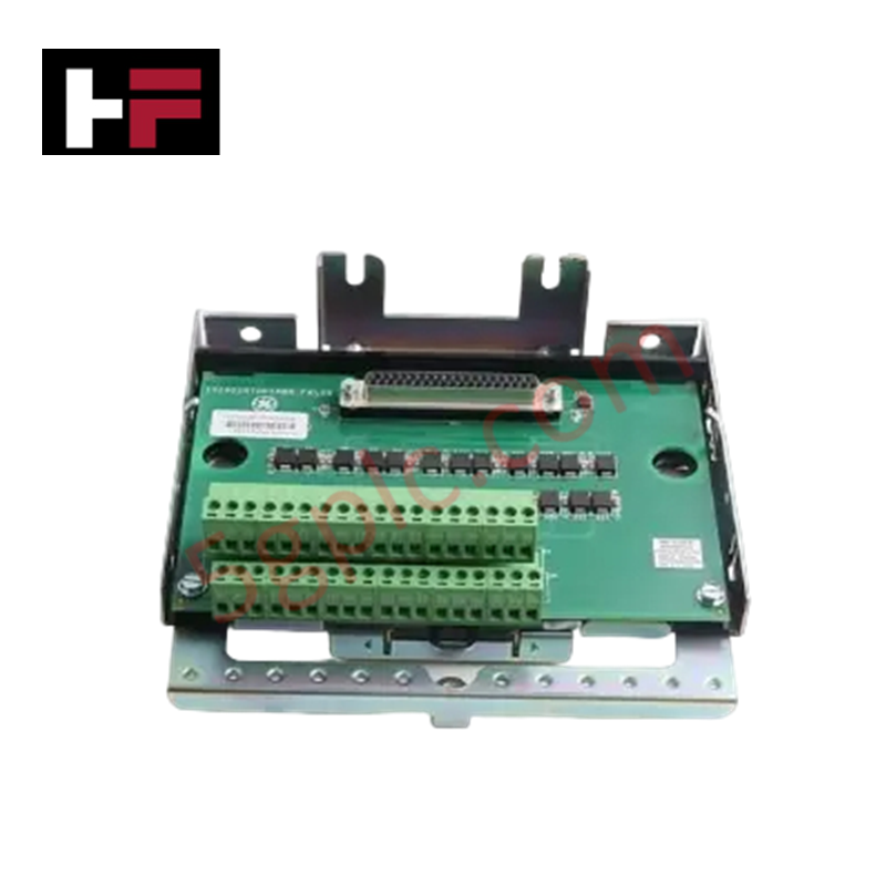
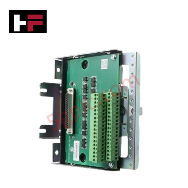
Tech & Buying Guide
Redundant Automation Systems: Maximizing Uptime in Critical Control Applications
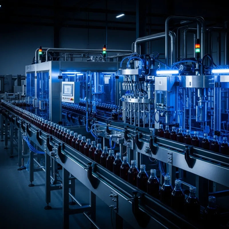
Industrial automation relies on continuous operational stability to prevent catastrophic downtime and financial loss. While standard dictionary definitions treat redundancy as superfluous, industrial engineers consider redundant control architectures indispensable for high-availability systems. Implementing backup hardware ensures seamless takeover during primary equipment failures, protecting critical infrastructure across manufacturing and process industries.
Demystifying the 5 Levels of Industrial Automation Architecture
Modern manufacturing relies on structured communication hierarchy to bridge physical shop-floor hardware with enterprise management software. This framework, commonly known as the Automation Pyramid, establishes how data flows between field devices, logic controllers, and corporate IT networks. Understanding these five distinct levels helps engineers and plant managers optimize system operations, reduce downtime, and implement seamless factory automation solutions.

Transforming Shop Floor Data into Actionable Insights: A Deep Dive into MES
Manufacturing Execution Systems serve as the digital backbone of modern factory floors. Positioned at Level 3 of the ISA-95 automation pyramid, MES links enterprise resource planning with real-time shop floor control systems. Today, industrial operators rely on MES software to bridge operational strategy with physical production execution.