










Product Details
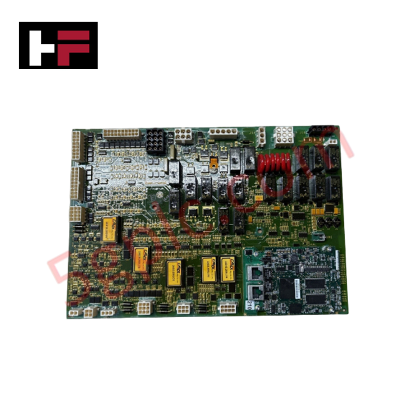
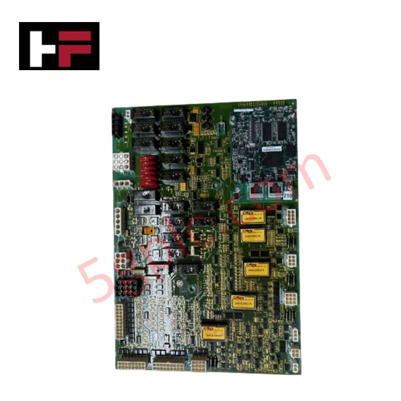
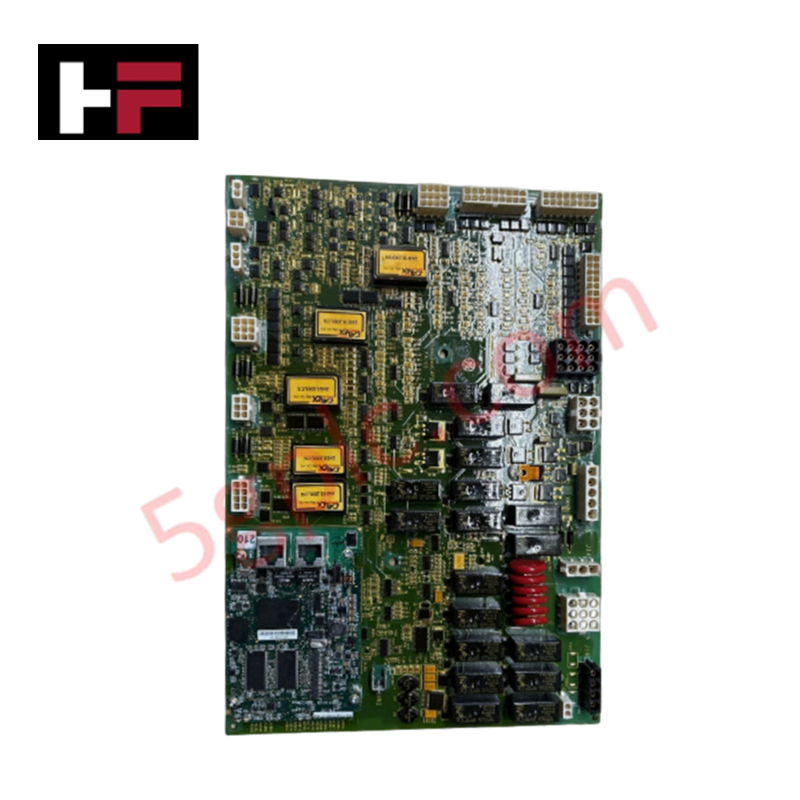
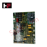
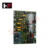
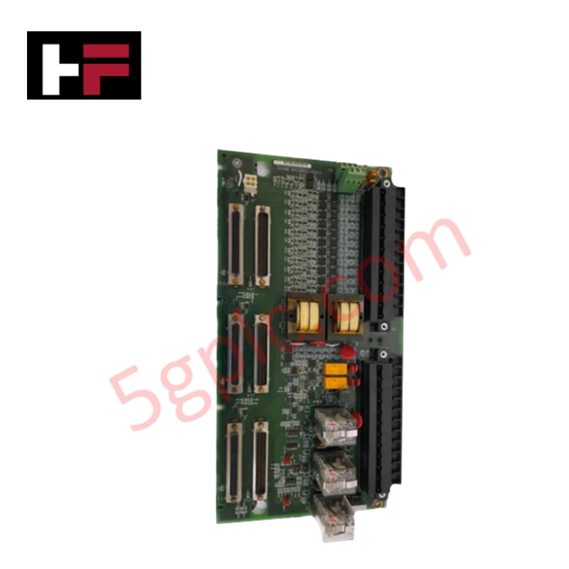
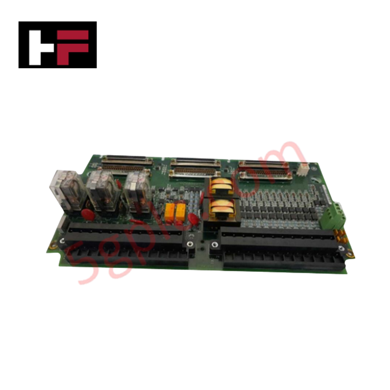
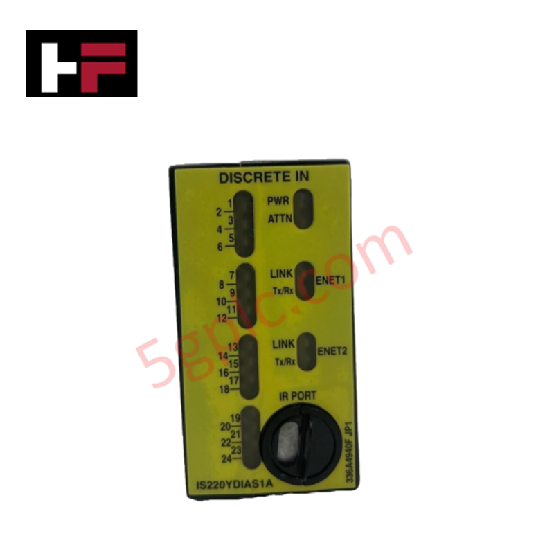
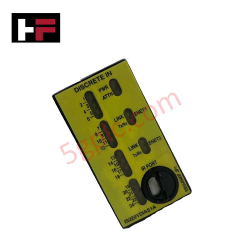
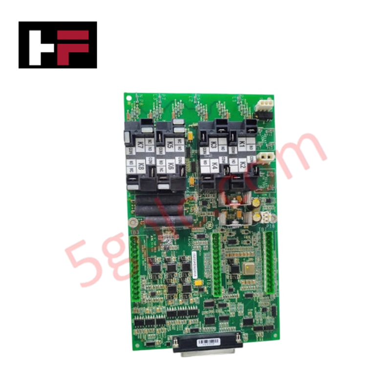
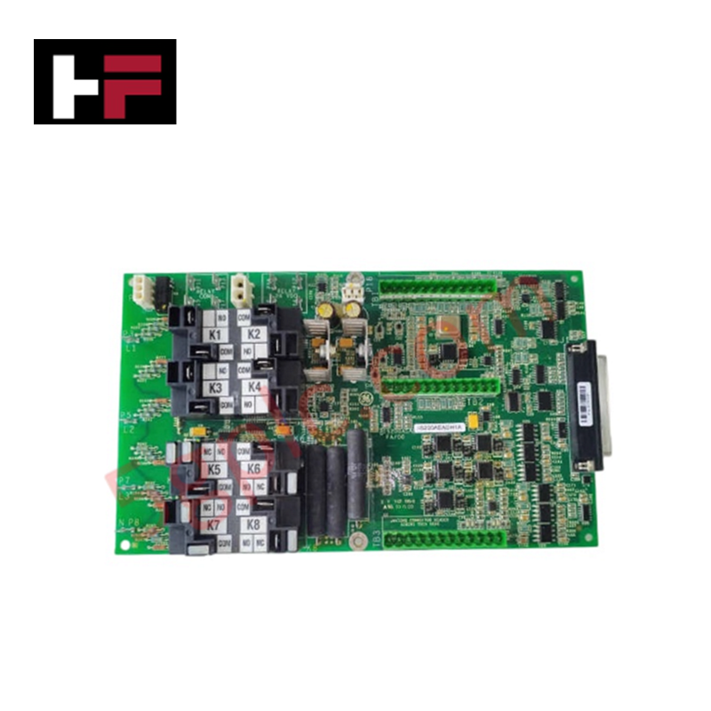
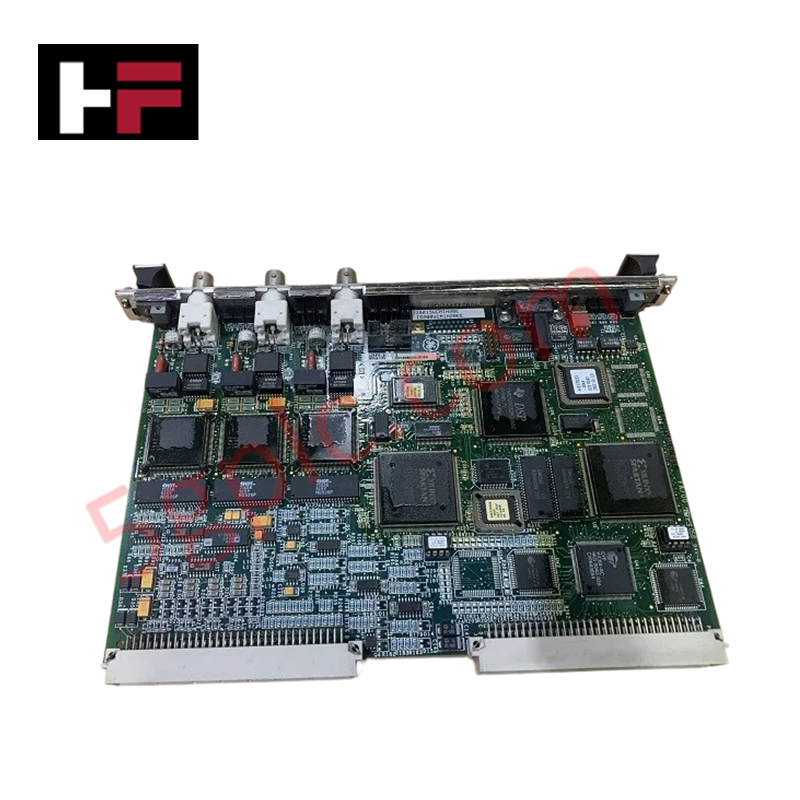
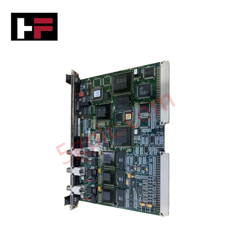
The GE IS200AEPAH1AEC, also cataloged as the IS200AEPAH1A Alternative Energy Pitch Axis (AEPA) board, operates as a dedicated hardware component for wind turbine blade pitch regulation and motion execution within GE Mark VIe control platforms.
Hardware Specifications
| Parameter | Specification |
|---|---|
| Model | IS200AEPAH1AEC |
| Brand | GE Energy |
| Origin | USA |
| Weight | 0.85 kg |
| Dimensions | 280 x 210 x 45 mm |
| Operating Temp | -30 to 65 deg C |
| Power Consumption | 15 W (Nominal) |
| Board Coating | Conformal Coated |
| Functional Revision | Revision Grade A |
| Analog Inputs | 8 channels |
| Analog Outputs | 1 channel |
| Discrete Inputs | 20 channels |
| Discrete Outputs | 1 channel |
| Relay Outputs | 8 channels (12 relays total on board) |
| Encoder Support | 1 Incremental Encoder Input, 1 Absolute Encoder Input |
| Serial Interfaces | 2 x RS-485 interfaces |
| Specialized Control | 1 Brake Control Output |
| Transient Protection | 6 Metal Oxide Varistors (MOVs) in-line |
Backplane Bus Communication and Firmware Flash Compatibility
The IS200AEPAH1AEC interfaces directly with the primary processing engine via twin male pin headers located on the upper-left section of the assembly. High-speed signal transfer across the internal rack bus relies on deterministic timing synchronization to prevent servo loop phase delays during pitch adjustments. Board-level firmware flash compatibility ensures seamless instruction set execution across Mark VIe system releases. Digital signal channels feature embedded filtering to mitigate transient electrical noise from high-power wind turbine pitch drives, maintaining steady-state feedback loops during volatile grid events.
Frequently Asked Questions
Q: How does the auxiliary board mount physically to the primary AEPA assembly?
A: The auxiliary board secures to the main PCB via mechanical standoffs and threaded screws. Inter-board electrical continuity passes through dedicated multi-pin headers to avoid strain on solder points.
Q: What mechanisms protect the I/O channels against overvoltage spikes?
A: Six inline metal oxide varistors (MOVs) clamp transient voltage surges across field wiring terminals. These non-linear variable resistors suppress inductive kickback from dynamic braking modules and field contactors.
Q: Are the onboard connectors configured for specific field wiring densities?
A: Seventeen vertical female-pin connectors ranging from 2-pin to 20-pin pinouts border the PCB perimeter, providing dedicated pin assignment paths for encoders, discrete feedback lines, and RS-485 serial buses.
Field Installation Guidelines
Ensure total electrical isolation and verify zero potential across power buses before insertion or removal. Mount the PCB in a sealed, temperature-controlled drive cabinet using metallic standoffs to establish a chassis ground path through the plated mounting holes. Wire encoder and analog feedback connections using twisted-pair shielded cables to prevent signal cross-talk. Route low-voltage RS-485 communication lines in separate conduit paths away from high-current motor leads. Maintain proper ESD grounding procedures, including grounded wrist straps, when handling uncontained boards during maintenance.
Additional Information
- 100% Genuine Parts: All products are original and authentic, ensuring reliable industrial performance.
- 30-Day Refund Guarantee: Return any in-stock item within 30 days in original, unopened packaging for a full refund (excluding shipping and fees).
- 12-Month Warranty: Covers defects in materials or workmanship; excludes misuse, normal wear, or unauthorized modifications.
- Worldwide Shipping: We ship via USPS, UPS, FedEx, and DHL. Delivery times vary by country and may be subject to customs or import fees.
- Support & Contact: Technical and warranty assistance is available anytime. Contact us here: Contact.
- Purchase Guidance: Check product specifications and compatibility carefully before ordering to ensure proper application.
Tech & Buying Guide

Mitigating Emergency Stop Spurious Trips in Industrial Control Systems
Emergency stop (E-Stop) pushbuttons serve as vital safety devices in factory automation and process control plants. Functional safety standards mandate normally-closed (NC) contact blocks to ensure fail-safe operation during wiring breaks or power outages. However, mechanical degradation over time can trigger unexpected spurious trips, halting production lines without an actual emergency. Understanding the underlying causes of mechanical contact failure allows automation engineers to implement robust, fault-tolerant safety circuits.

Redundant Automation Systems: Maximizing Uptime in Critical Control Applications
Industrial automation relies on continuous operational stability to prevent catastrophic downtime and financial loss. While standard dictionary definitions treat redundancy as superfluous, industrial engineers consider redundant control architectures indispensable for high-availability systems. Implementing backup hardware ensures seamless takeover during primary equipment failures, protecting critical infrastructure across manufacturing and process industries.
Demystifying the 5 Levels of Industrial Automation Architecture
Modern manufacturing relies on structured communication hierarchy to bridge physical shop-floor hardware with enterprise management software. This framework, commonly known as the Automation Pyramid, establishes how data flows between field devices, logic controllers, and corporate IT networks. Understanding these five distinct levels helps engineers and plant managers optimize system operations, reduce downtime, and implement seamless factory automation solutions.