











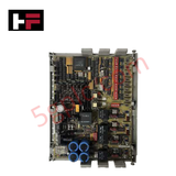
Product Details
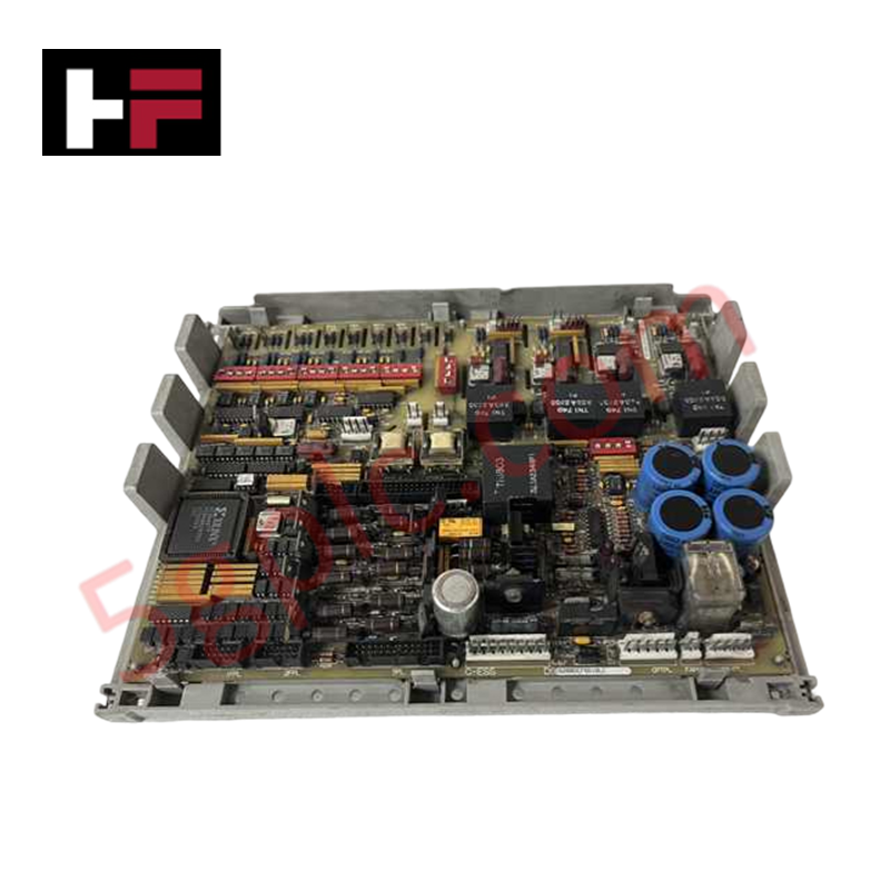
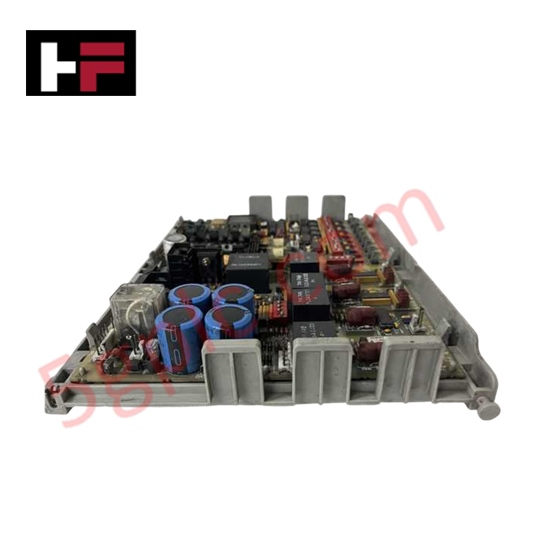
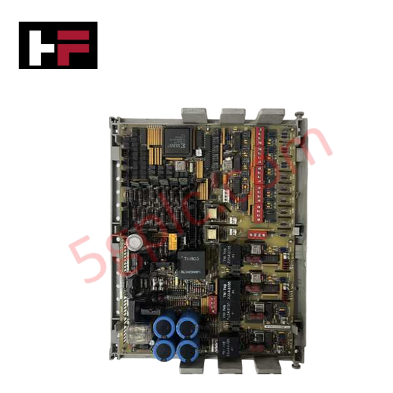
Configured for power conversion and regulation in EX2000, DC2000, and associated drive platforms, the GE DS200DCFBG1BLC (DS200DCFBG1 DC Power Supply Feedback Board) provides direct physical power distribution and control-level voltage regulation.
Hardware Specifications
| Parameter | Specification |
|---|---|
| Model | DS200DCFBG1BLC |
| Brand | General Electric |
| Origin | USA |
| Operating Temp | -10 deg C to +70 deg C |
| Power Consumption | Not specified |
| Input Voltage | 38 V AC and 115 V AC (derived from CPT) |
| Output Voltage | +5 V DC, +/- 15 V DC, +/- 24 V DC |
Industrial Control & Firmware Compatibility
The DS200DCFBG1BLC serves as the primary power management interface for drive control processors, utilizing an integrated regulation circuit to maintain deterministic voltage levels. The board supports I/O density scaling through its dedicated motor field power circuits and gate pulse generator drivers. Firmware flash compatibility is governed by the drive control board (SDCC/LDCC), which monitors the /PSEN signal; this signal triggers a micro-processor reset if the onboard +5 V DC supply deviates from regulation, ensuring system-wide stability during input power fluctuations.
Frequently Asked Questions
Q: How does the /PSEN signal interact with the drive controller?
A: The /PSEN signal on terminal 2PL monitors the +5 V DC regulation state. When the supply is within limits, the signal is at a TTL low state. If the output voltage drops out of regulation, the signal transitions to a high state, initiating a hardware reset on the Drive Control Card.
Q: What is the load capacity for the +/- 15 V DC outputs?
A: Each +/- 15 V DC output is rated at 0.8 A. Of this total current capacity, 0.25 A is available for external loading beyond the requirements of the board's internal circuitry.
Field Installation Guidelines
- Input Power Verification: Before energizing, verify that the Control Power Transformer (CPT) outputs are stable at 38 V AC (+10%). Incorrect input voltage levels will prevent the internal full-wave rectification and filtering circuits from producing the required unregulated +/- 24 V DC levels.
- Component Handling: Ensure all field wiring is disconnected before board removal. When installing, ensure the board is securely fastened to the chassis to maintain the ground reference required for the feedback circuits.
- Shielding and Grounding: To maintain signal integrity of the SCR gate pulse generators and feedback loops, ensure that cable shields are properly terminated at the enclosure ground points to prevent electromagnetic interference from affecting the power regulation outputs.
Additional Information
- 100% Genuine Parts: All products are original and authentic, ensuring reliable industrial performance.
- 30-Day Refund Guarantee: Return any in-stock item within 30 days in original, unopened packaging for a full refund (excluding shipping and fees).
- 12-Month Warranty: Covers defects in materials or workmanship; excludes misuse, normal wear, or unauthorized modifications.
- Worldwide Shipping: We ship via USPS, UPS, FedEx, and DHL. Delivery times vary by country and may be subject to customs or import fees.
- Support & Contact: Technical and warranty assistance is available anytime. Contact us here: Contact.
- Purchase Guidance: Check product specifications and compatibility carefully before ordering to ensure proper application.


Tech & Buying Guide

Comprehensive Guide to Noise Types in Industrial Automation and Electronics

Mitigating Emergency Stop Spurious Trips in Industrial Control Systems
Emergency stop (E-Stop) pushbuttons serve as vital safety devices in factory automation and process control plants. Functional safety standards mandate normally-closed (NC) contact blocks to ensure fail-safe operation during wiring breaks or power outages. However, mechanical degradation over time can trigger unexpected spurious trips, halting production lines without an actual emergency. Understanding the underlying causes of mechanical contact failure allows automation engineers to implement robust, fault-tolerant safety circuits.
Redundant Automation Systems: Maximizing Uptime in Critical Control Applications
Industrial automation relies on continuous operational stability to prevent catastrophic downtime and financial loss. While standard dictionary definitions treat redundancy as superfluous, industrial engineers consider redundant control architectures indispensable for high-availability systems. Implementing backup hardware ensures seamless takeover during primary equipment failures, protecting critical infrastructure across manufacturing and process industries.