










Product Details
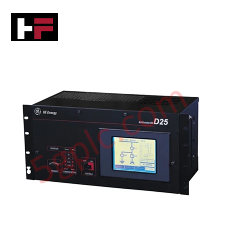
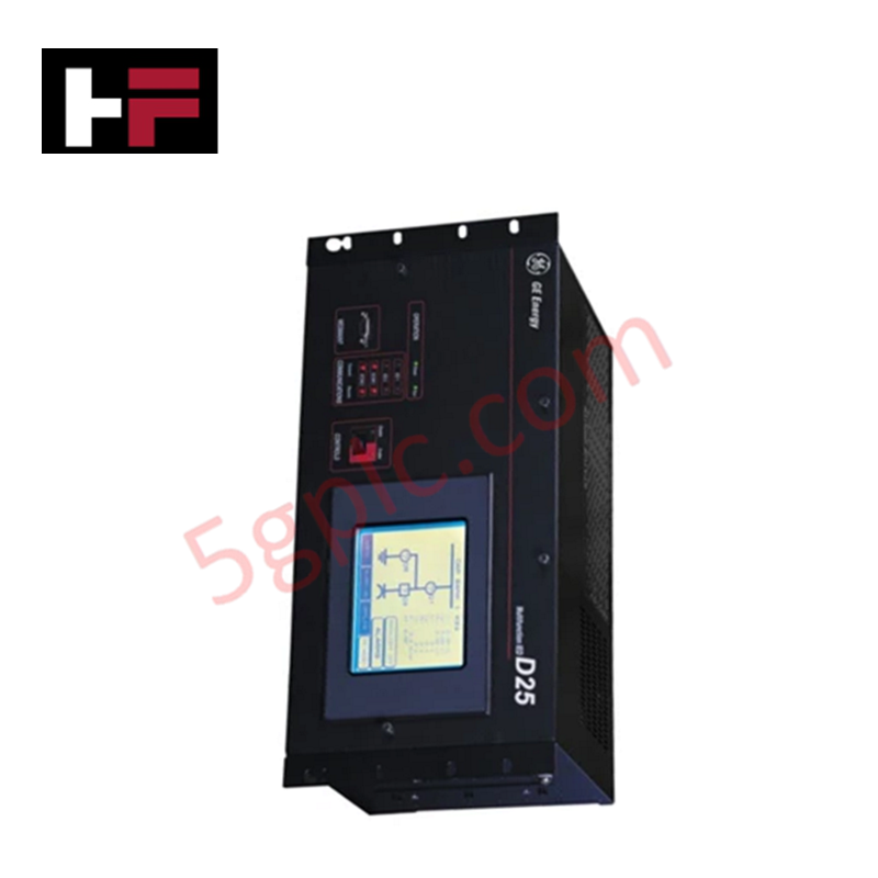
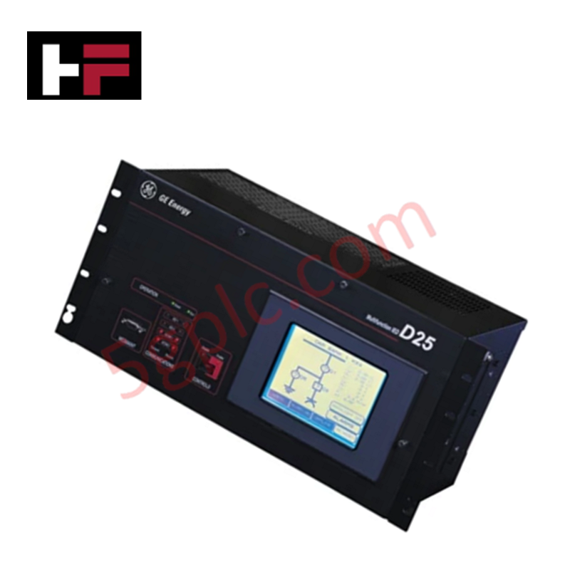
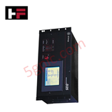
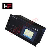
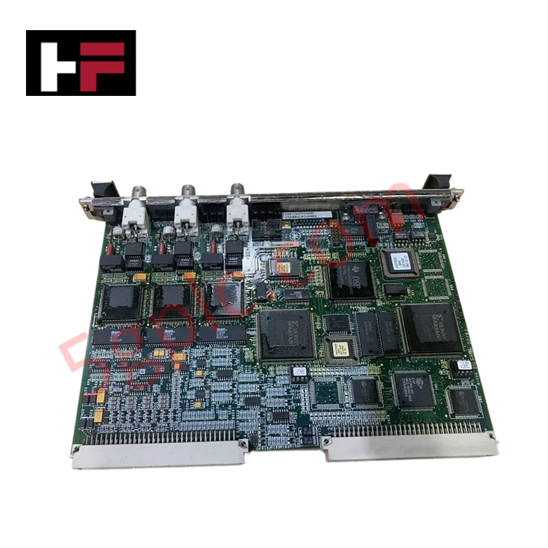
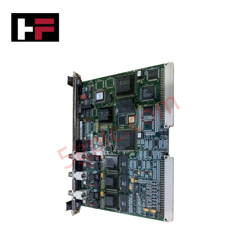
The GE FANUC D25-0159-000001, also cataloged as the D25 Monitoring and Control Device, operates as a dedicated hardware component for specific technical task execution within industrial automation and network platforms. The device directly handles 32 digital inputs and 16 analog inputs (0-10 V) to monitor field parameters, while driving electrical loops through 16 digital outputs and 8 analog outputs (0-10 V). Data communication flows via Ethernet and RS-485 interfaces utilizing the Modbus protocol, supported by a dual-display interface comprising a 7-inch touchscreen and a 4-line LCD.
Hardware Specifications
| Parameter | Specification |
|---|---|
| Model | D25-0159-000001 |
| Brand | GE FANUC |
| Origin | Technical specifications determine final factory origin |
| Weight | 5 pounds (2.3 kg) |
| Dimensions | 10 inches x 7 inches x 2 inches (254 mm x 178 mm x 51 mm) |
| Operating Temp | 0 to 50 deg C (32 to 122 deg F) |
| Power Consumption | Determined by active I/O load and voltage selection |
| Power Supply | 110/220 VAC, 50/60 Hz |
| Humidity | 10% to 90% RH, non-condensing |
| Digital Inputs | 32 channels |
| Analog Inputs | 16 channels (0-10 V) |
| Digital Outputs | 16 channels |
| Analog Outputs | 8 channels (0-10 V) |
| Communication Interfaces | Ethernet, RS-485 |
| Protocol Support | Modbus |
| Dual Interface System | 7-inch touchscreen graphical panel and 4-line LCD data display |
Firmware Flash Compatibility and I/O Density Scaling
The internal controller board governs processing logic through local memory architectures that require exact firmware flash compatibility matching during system initialization. When handling maximum channel capacities, the device runs localized logic execution cycles that scale without data buffer overflows. The processing sequence separates serial communication requests over Modbus from the hardware scanning cycles of the high-density digital and analog I/O blocks, preventing runtime timing errors and bus delays.
Frequently Asked Questions
Q: Can the internal I/O terminal logic boards be serviced or hot-swapped while the 110/220 VAC power source is connected?
A: No. The internal logic pins and terminal interfaces do not support live hot-swapping. The 110/220 VAC power supply must be entirely disconnected from the power terminals before attempting any maintenance to avoid risk of electrical shock or logic component failure.
Q: How does the dual-display architecture process simultaneous touchscreen and 4-line LCD updates?
A: The internal processing core allocates separate display-refresh registers to the 7-inch graphical touchscreen and the 4-line LCD data display. This hardware division allows real-time data monitoring to continue on the LCD without logic loop interruption while the touchscreen processes input parameters.
Field Installation Guidelines
- Earthing and Chassis Grounding: Attach a dedicated low-impedance grounding copper conductor from the chassis ground screw directly to the main control panel earth ground bus bar.
- Signal Line Shielding: Run all 0-10 V analog input and output loops using shielded twisted-pair cables, ensuring that the cable shields are grounded at the enclosure side only to prevent ground loop currents.
- Conduit and Wiring Isolation: Route all high-voltage 110/220 VAC power lines in separate metal conduits away from low-voltage digital signal wiring, RS-485 lines, and Ethernet communication cables.
Additional Information
- 100% Genuine Parts: All products are original and authentic, ensuring reliable industrial performance.
- 30-Day Refund Guarantee: Return any in-stock item within 30 days in original, unopened packaging for a full refund (excluding shipping and fees).
- 12-Month Warranty: Covers defects in materials or workmanship; excludes misuse, normal wear, or unauthorized modifications.
- Worldwide Shipping: We ship via USPS, UPS, FedEx, and DHL. Delivery times vary by country and may be subject to customs or import fees.
- Support & Contact: Technical and warranty assistance is available anytime. Contact us here: Contact.
- Purchase Guidance: Check product specifications and compatibility carefully before ordering to ensure proper application.
Tech & Buying Guide
Mitigating Emergency Stop Spurious Trips in Industrial Control Systems
Emergency stop (E-Stop) pushbuttons serve as vital safety devices in factory automation and process control plants. Functional safety standards mandate normally-closed (NC) contact blocks to ensure fail-safe operation during wiring breaks or power outages. However, mechanical degradation over time can trigger unexpected spurious trips, halting production lines without an actual emergency. Understanding the underlying causes of mechanical contact failure allows automation engineers to implement robust, fault-tolerant safety circuits.
Redundant Automation Systems: Maximizing Uptime in Critical Control Applications
Industrial automation relies on continuous operational stability to prevent catastrophic downtime and financial loss. While standard dictionary definitions treat redundancy as superfluous, industrial engineers consider redundant control architectures indispensable for high-availability systems. Implementing backup hardware ensures seamless takeover during primary equipment failures, protecting critical infrastructure across manufacturing and process industries.
Demystifying the 5 Levels of Industrial Automation Architecture
Modern manufacturing relies on structured communication hierarchy to bridge physical shop-floor hardware with enterprise management software. This framework, commonly known as the Automation Pyramid, establishes how data flows between field devices, logic controllers, and corporate IT networks. Understanding these five distinct levels helps engineers and plant managers optimize system operations, reduce downtime, and implement seamless factory automation solutions.