










Product Details
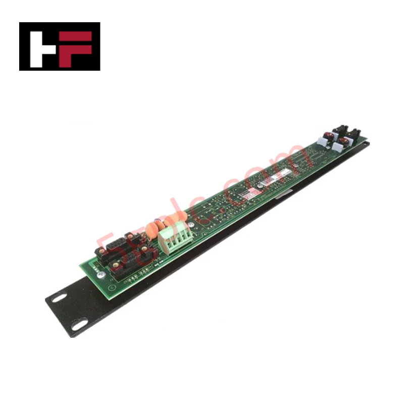
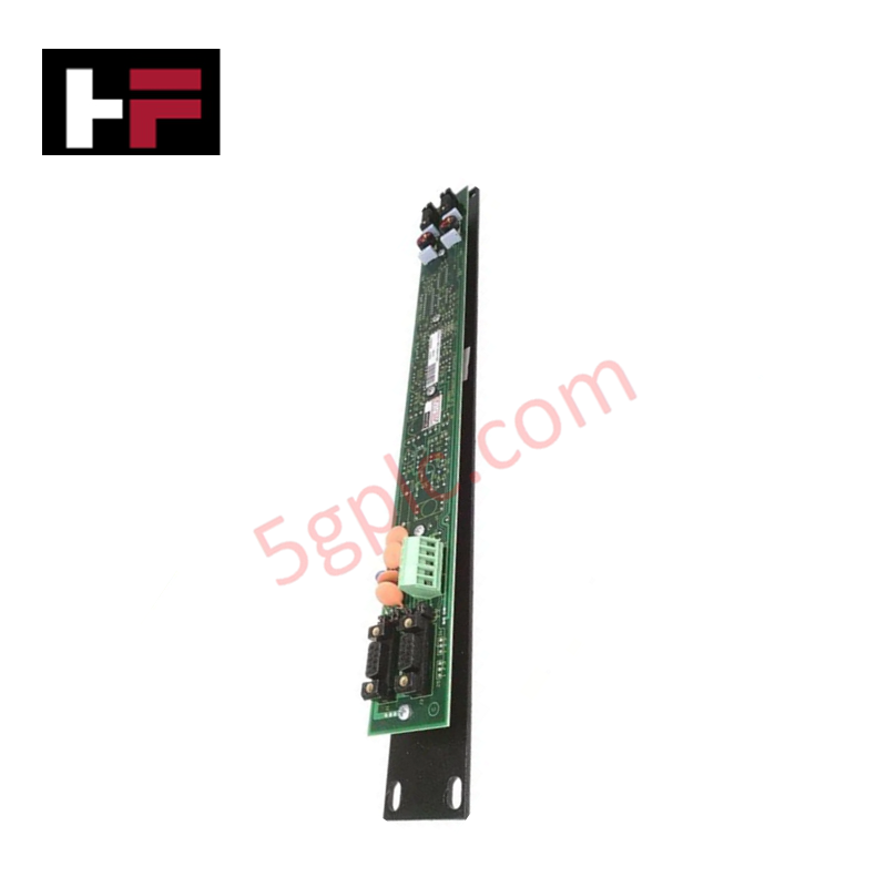
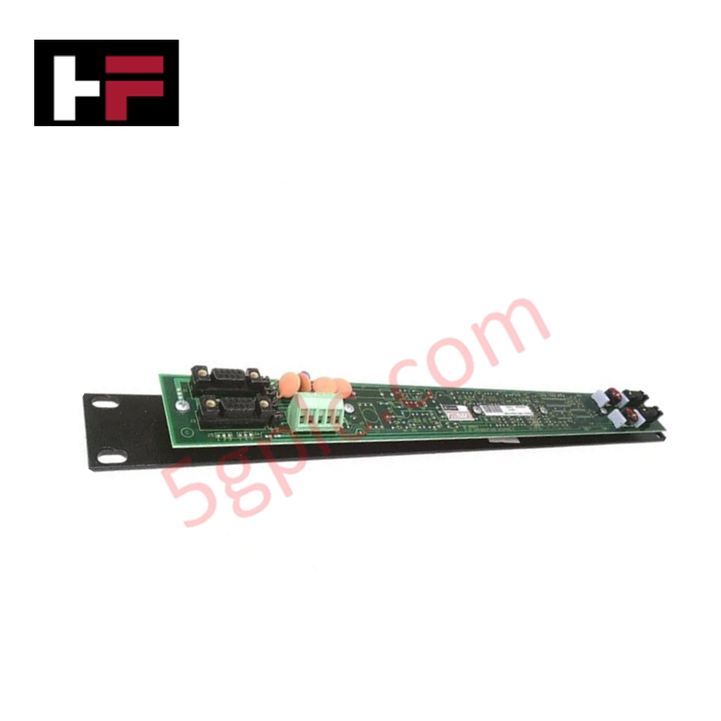
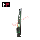
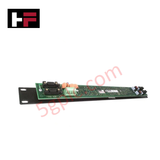
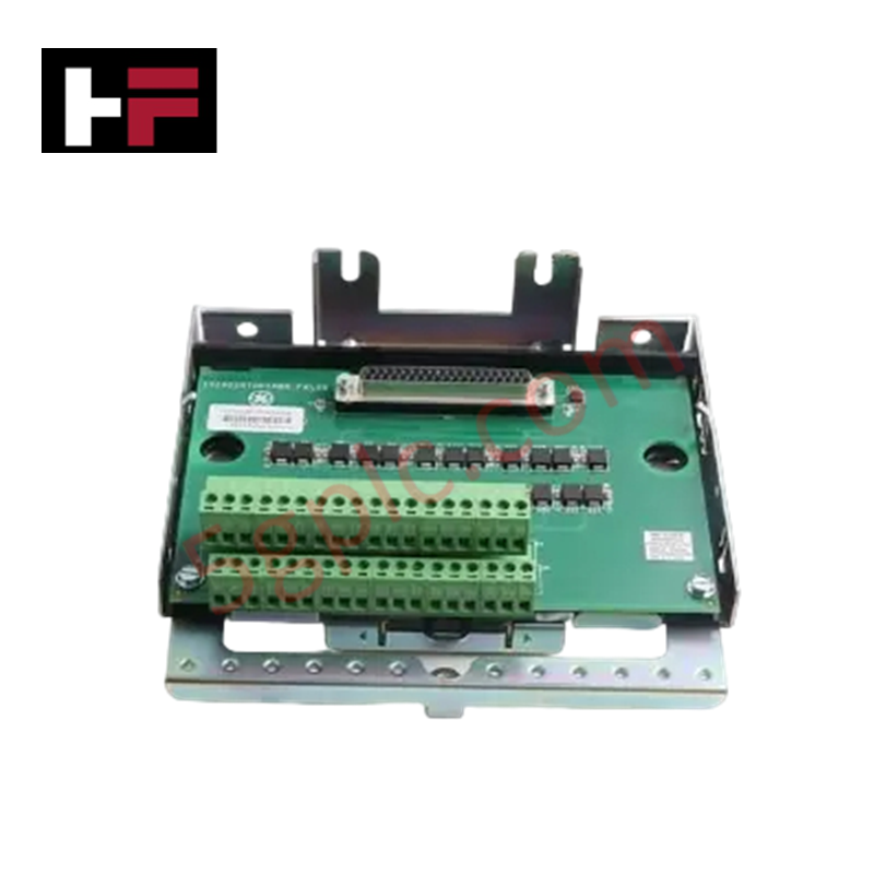
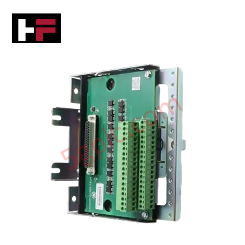
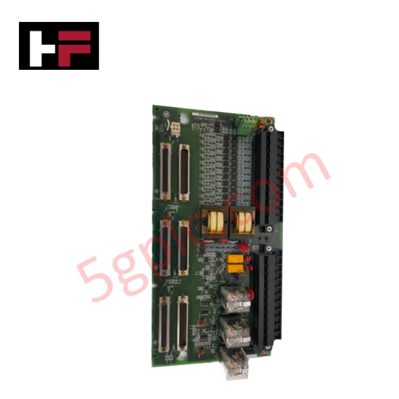
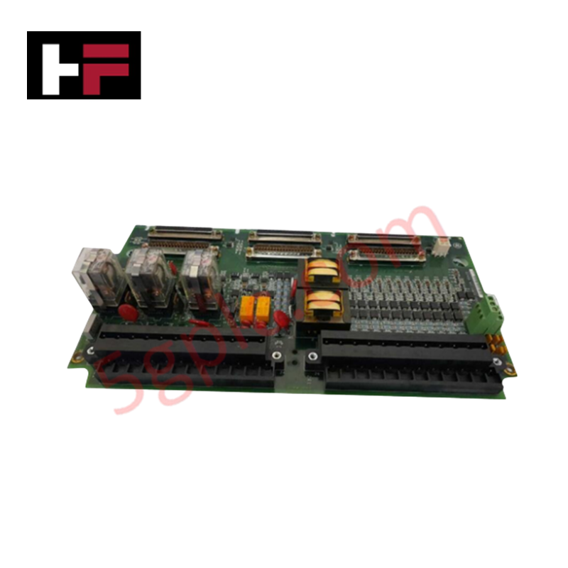
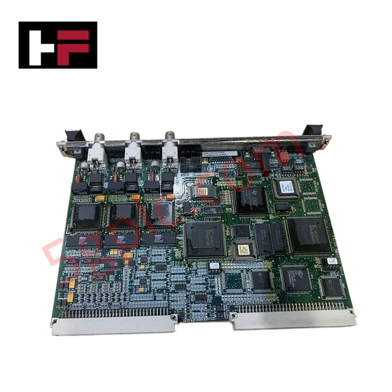
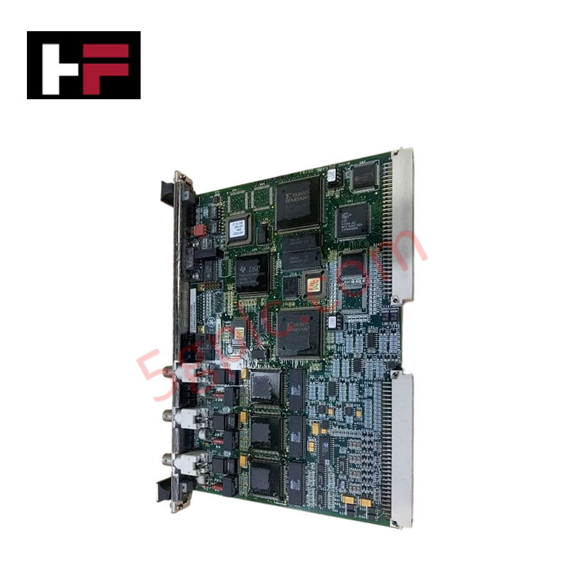
The GE 520-0154, also cataloged as the 520-0154 VersaMax I/O Carrier, operates as a dedicated hardware component for backplane bus interface connection and field signal terminal routing within GE VersaMax I/O systems.
Hardware Specifications
| Parameter | Specification |
|---|---|
| Model | 520-0154 |
| Brand | GE / GE Fanuc |
| Origin | USA |
| Weight | 0.25 kg |
| Dimensions | 134 x 70 x 45 mm |
| Operating Temp | 0 to +60 deg C |
| Power Consumption | Passive Component (0 W Base Draw) |
| Mounting Type | 35 mm DIN-Rail / Panel Mount |
| Terminal Type | Field Wiring Terminal Block Interface |
| System Compatibility | GE Fanuc VersaMax I/O Series |
Backplane Bus Communication Velocity and I/O Density Scaling
The 520-0154 carrier establishes the passive electrical backplane connection that enables high backplane bus communication velocity between adjacent VersaMax modules. By decoupling field wiring terminations from the active I/O processing module, the carrier supports high-density panel installations while maintaining physical channel isolation. Onboard passive trace routing maintains firmware flash compatibility across standard VersaMax I/O modules without introducing communication latencies or signal distortion across the local expansion bus.
Frequently Asked Questions
Q: Can VersaMax I/O modules be hot-swapped from the 520-0154 carrier during active operation?
A: Yes, the active I/O module can be removed and replaced from the 520-0154 carrier without disconnecting field wiring or interrupting the backplane bus pass-through to adjacent modules, provided system power considerations are observed.
Q: Does the 520-0154 carrier require an external 24 VDC power connection to operate?
A: No, the carrier is a passive wiring substrate. Power is delivered to field terminals and active modules via the Network Interface Unit (NIU) or Power Supply Module connected to the VersaMax backplane stack.
Field Installation Guidelines
- Snap the 520-0154 carrier firmly onto a standard 35 mm DIN-rail, ensuring the DIN-rail latch engages completely.
- Connect adjacent VersaMax carriers by sliding them together laterally until the backplane bus connectors click into full engagement.
- Strip field wires 8 mm to 10 mm and terminate them into the designated carrier screw or spring terminals, adhering to the wiring diagram for the specific I/O module being used.
- Verify all field wiring shields are grounded at a single Earth ground point to prevent ground loops and electromagnetic interference.
- Align the active VersaMax I/O module over the 520-0154 carrier guide pins and press straight down until the latch mechanism locks the module into place.
Additional Information
- 100% Genuine Parts: All products are original and authentic, ensuring reliable industrial performance.
- 30-Day Refund Guarantee: Return any in-stock item within 30 days in original, unopened packaging for a full refund (excluding shipping and fees).
- 12-Month Warranty: Covers defects in materials or workmanship; excludes misuse, normal wear, or unauthorized modifications.
- Worldwide Shipping: We ship via USPS, UPS, FedEx, and DHL. Delivery times vary by country and may be subject to customs or import fees.
- Support & Contact: Technical and warranty assistance is available anytime. Contact us here: Contact.
- Purchase Guidance: Check product specifications and compatibility carefully before ordering to ensure proper application.
Tech & Buying Guide
Demystifying the 5 Levels of Industrial Automation Architecture
Modern manufacturing relies on structured communication hierarchy to bridge physical shop-floor hardware with enterprise management software. This framework, commonly known as the Automation Pyramid, establishes how data flows between field devices, logic controllers, and corporate IT networks. Understanding these five distinct levels helps engineers and plant managers optimize system operations, reduce downtime, and implement seamless factory automation solutions.

Transforming Shop Floor Data into Actionable Insights: A Deep Dive into MES
Manufacturing Execution Systems serve as the digital backbone of modern factory floors. Positioned at Level 3 of the ISA-95 automation pyramid, MES links enterprise resource planning with real-time shop floor control systems. Today, industrial operators rely on MES software to bridge operational strategy with physical production execution.
