










Product Details
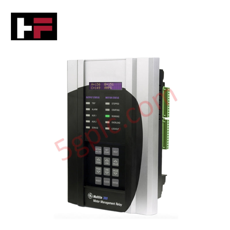
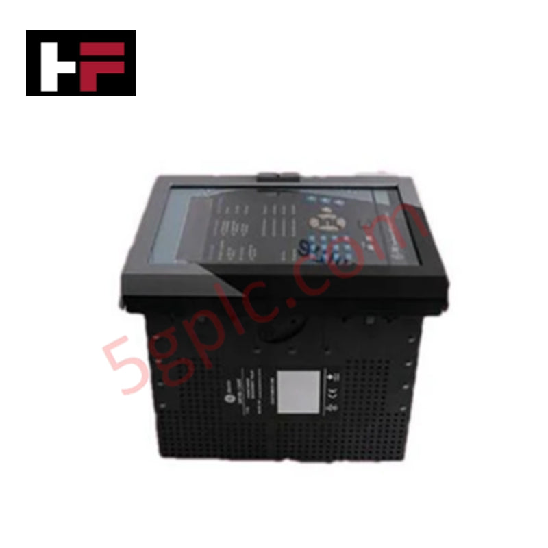
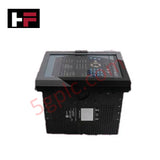
The GE 369-HI-0-0-0-0-0-E, also cataloged as the 369 Motor Protection Relay, operates as a dedicated hardware component for motor monitoring, fault detection, and thermal overload protection within GE Multilin 369 Motor Management System platforms.
Hardware Specifications
| Parameter | Specification |
|---|---|
| Model | 369-HI-0-0-0-0-0-E |
| Brand | GE / GE Multilin |
| Origin | USA |
| Operating Temp | -20 to +60 deg C |
| Power Consumption | Control Power: 50-300 VDC / 60-265 VAC |
| Display Interface | Enhanced LED-Backlit Display Window |
| User Interface | 12 Front-Panel Labeled Push Buttons |
| Diagnostic Status | 10 Labeled Front-Panel LED Indicators |
| Environmental Rating | Non-Harsh Environment (Standard Conformal/Enclosure) |
Backplane Bus Communication Velocity and Firmware Flash Compatibility
The 369-HI-0-0-0-0-0-E utilizes an internal micro-controller architecture to process phase currents, ground faults, and thermal models in real time. Backplane bus communication velocity is maintained across high-speed serial links, ensuring rapid trip signal output execution during overcurrent or phase imbalance conditions. The internal memory supports firm, verified firmware flash compatibility to allow seamless integration into automated power management networks without risking configuration drift or protocol mismatch.
Frequently Asked Questions
Q: Does the 369-HI-0-0-0-0-0-E support direct connection of RTD temperature sensors?
A: No. The second "0" in the model matrix indicates that the 12 built-in RTD inputs are absent on this hardware option. External RTD module expansion is required if direct temperature sensing is needed.
Q: What control power voltage ranges are supported by the "HI" power supply option?
A: The "HI" power supply option accepts either 50-300 VDC or 60-265 VAC at 50/60 Hz control power sources.
Field Installation Guidelines
- De-energize all high-voltage feeder circuits and control power sources before installing or servicing the relay.
- Mount the 369-HI-0-0-0-0-0-E securely in the switchgear panel cutout using the four backplane mounting screws.
- Connect dedicated Earth ground to the rear panel ground terminal using minimum 12 AWG copper wire to ensure EMI shielding and electrical safety.
- Wire the 50-300 VDC / 60-265 VAC control power lines to the designated power terminals using shielded wire runs.
- Terminate current transformer (CT) secondary leads securely, ensuring proper shorting blocks are utilized prior to disconnecting any secondary loop.
- Verify all terminal connection torques and ensure front-panel LED diagnostics illuminate correctly during power-on initialization.
Additional Information
- 100% Genuine Parts: All products are original and authentic, ensuring reliable industrial performance.
- 30-Day Refund Guarantee: Return any in-stock item within 30 days in original, unopened packaging for a full refund (excluding shipping and fees).
- 12-Month Warranty: Covers defects in materials or workmanship; excludes misuse, normal wear, or unauthorized modifications.
- Worldwide Shipping: We ship via USPS, UPS, FedEx, and DHL. Delivery times vary by country and may be subject to customs or import fees.
- Support & Contact: Technical and warranty assistance is available anytime. Contact us here: Contact.
- Purchase Guidance: Check product specifications and compatibility carefully before ordering to ensure proper application.
Tech & Buying Guide
Demystifying the 5 Levels of Industrial Automation Architecture
Modern manufacturing relies on structured communication hierarchy to bridge physical shop-floor hardware with enterprise management software. This framework, commonly known as the Automation Pyramid, establishes how data flows between field devices, logic controllers, and corporate IT networks. Understanding these five distinct levels helps engineers and plant managers optimize system operations, reduce downtime, and implement seamless factory automation solutions.

Transforming Shop Floor Data into Actionable Insights: A Deep Dive into MES
Manufacturing Execution Systems serve as the digital backbone of modern factory floors. Positioned at Level 3 of the ISA-95 automation pyramid, MES links enterprise resource planning with real-time shop floor control systems. Today, industrial operators rely on MES software to bridge operational strategy with physical production execution.
