










Product Details
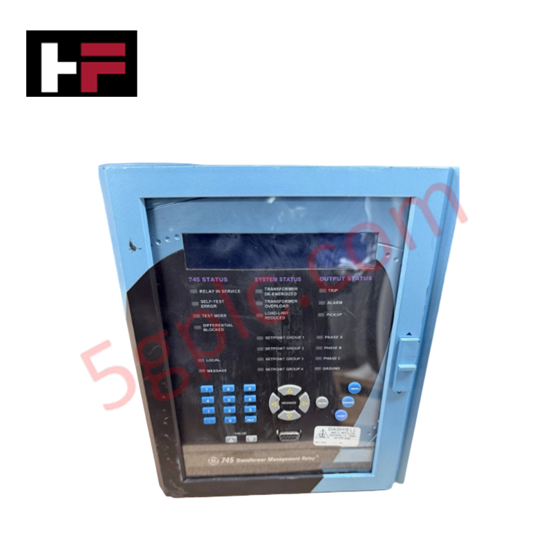
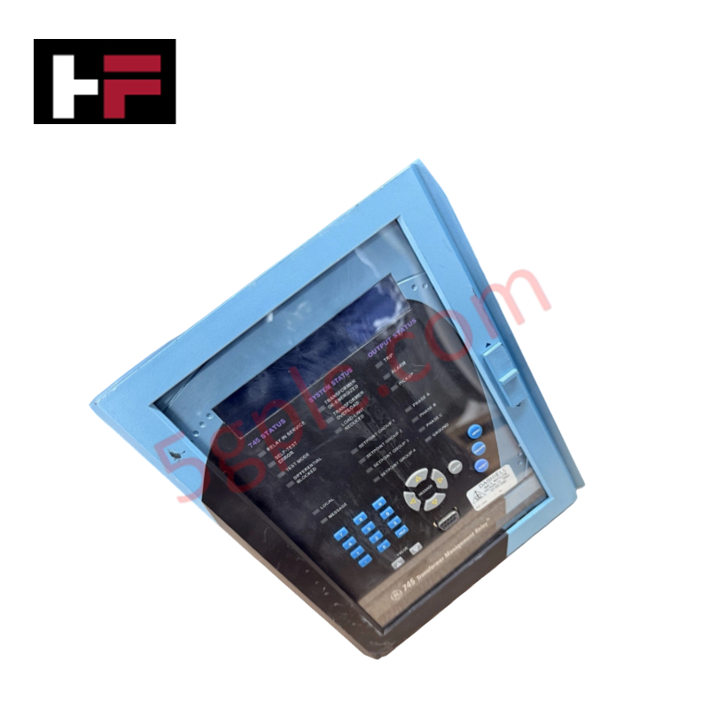
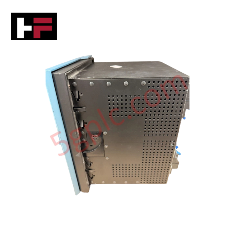
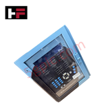
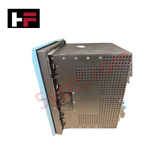
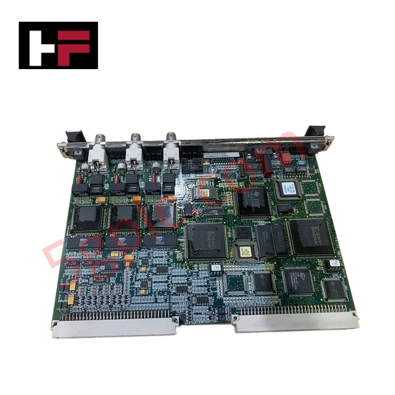
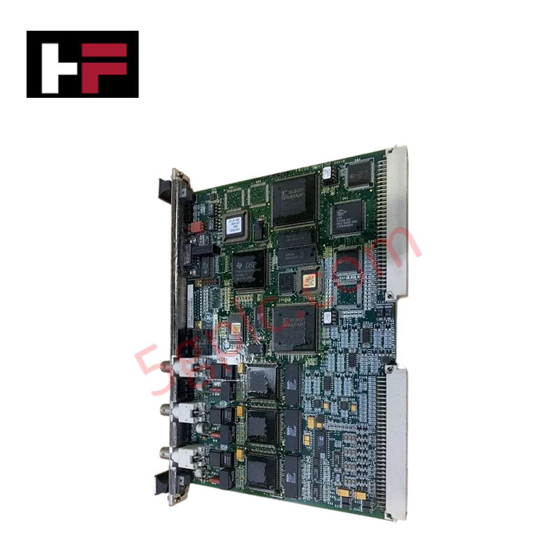
The GE 745-W2-P5-G1-HI-A, also cataloged as the GE 745 Transformer Protection Relay Module, operates as a dedicated hardware component for multi-winding current differential evaluation and fault actuation within utility substation power networks.
Hardware Specifications
| Parameter | Specification |
|---|---|
| Model | 745-W2-P5-G1-HI-A |
| Brand | GE Multilin |
| Origin | Canada / United States |
| Weight | Standard Relay Unit Weight |
| Dimensions | Standard 745 Series Chassis Profile |
| Operating Temp | -20 - +60 deg C |
| Power Consumption | HI Power Supply Option Dependent |
| Transformer Windings | 2 Winding configuration (W2) |
| Phase CT Input | 5 A secondary (P5) |
| Ground CT Input | 1 A / 5 A secondary (G1) |
| Protection Elements | 87T (Differential), 24 (Overexcitation), 49 (Thermal Overload) |
| Board Protection | Conformal coating layer |
| Local Interface | Enhanced LCD display with expanded keypad |
Firmware Flash Compatibility and Processing Architecture
The module computes phase current vectors and calculates differential metrics continuously across the 2-winding network structure. Real-time calculations of Total Harmonic Distortion (THD), frequency rate-of-change, and hottest spot thermal tracking are executed via an internal floating-point processor. To preserve execution synchronization and prevent buffer underruns during sequence-of-events logging, matching upstream substation SCADA properties with verified firmware flash compatibility benchmarks across all localized processing layers is mandatory.
Frequently Asked Questions
Q: How does the dynamic CT ratio mismatch correction behave during external fault states?
A: The internal processing matrix samples phase currents and normalizes scaling parameters mathematically based on configured winding entries every half-cycle. This internal optimization eliminates the requirement for external auxiliary matching current transformers.
Q: What is the function of the conformal coating modification on this specific hardware assembly?
A: The conformal coating layer isolates surface-mount components from atmospheric moisture, airborne conductive particulates, and corrosive chemical traces, preventing parasitic trace leakage and maintaining dielectric boundary integrity.
Field Installation Guidelines
- Chassis Grounding Connection: Attach a dedicated, low-impedance copper conductor from the rear panel safety ground lug directly to the local substation primary earth ground grid.
- Current Transformer Termination Layout: Route all 5 A phase and ground CT secondary loops through external shorting test blocks before connecting to the terminal block to allow safe maintenance tracking.
- Control Cable Segregation: Run all low-voltage analog signal lines through dedicated wireways isolated from the main alternating current (AC) or high-voltage direct current (DC) control power wiring to minimize electromagnetic noise coupling.
Additional Information
- 100% Genuine Parts: All products are original and authentic, ensuring reliable industrial performance.
- 30-Day Refund Guarantee: Return any in-stock item within 30 days in original, unopened packaging for a full refund (excluding shipping and fees).
- 12-Month Warranty: Covers defects in materials or workmanship; excludes misuse, normal wear, or unauthorized modifications.
- Worldwide Shipping: We ship via USPS, UPS, FedEx, and DHL. Delivery times vary by country and may be subject to customs or import fees.
- Support & Contact: Technical and warranty assistance is available anytime. Contact us here: Contact.
- Purchase Guidance: Check product specifications and compatibility carefully before ordering to ensure proper application.
Tech & Buying Guide
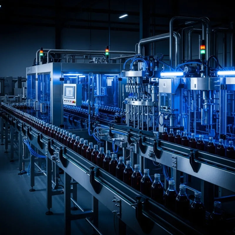
Redundant Automation Systems: Maximizing Uptime in Critical Control Applications
Industrial automation relies on continuous operational stability to prevent catastrophic downtime and financial loss. While standard dictionary definitions treat redundancy as superfluous, industrial engineers consider redundant control architectures indispensable for high-availability systems. Implementing backup hardware ensures seamless takeover during primary equipment failures, protecting critical infrastructure across manufacturing and process industries.
Demystifying the 5 Levels of Industrial Automation Architecture
Modern manufacturing relies on structured communication hierarchy to bridge physical shop-floor hardware with enterprise management software. This framework, commonly known as the Automation Pyramid, establishes how data flows between field devices, logic controllers, and corporate IT networks. Understanding these five distinct levels helps engineers and plant managers optimize system operations, reduce downtime, and implement seamless factory automation solutions.

Transforming Shop Floor Data into Actionable Insights: A Deep Dive into MES
Manufacturing Execution Systems serve as the digital backbone of modern factory floors. Positioned at Level 3 of the ISA-95 automation pyramid, MES links enterprise resource planning with real-time shop floor control systems. Today, industrial operators rely on MES software to bridge operational strategy with physical production execution.