










Product Details
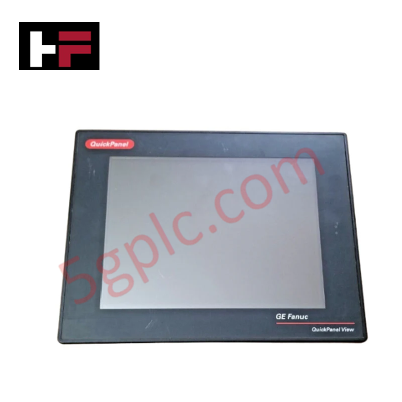
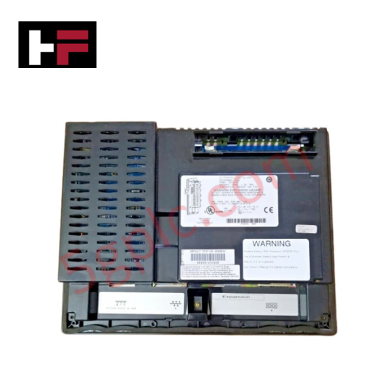
The General Electric IC755SUE10CTD, also cataloged as the IC755SUE10CTD Power Interface Component, operates as a dedicated hardware component for voltage step-down and electrical isolation within industrial control networks.
Hardware Specifications
| Parameter | Specification |
|---|---|
| Model | IC755SUE10CTD |
| Brand | General Electric (GE) |
| Origin | United States |
| Weight | Standard 10 kVA Enclosure Weight |
| Dimensions | Compact NEMA 1 Footprint |
| Operating Temp | 0 - 50 deg C |
| Power Consumption | Power Rating: 10 kVA |
| Transformer Type | Single-phase |
| Primary Voltage | 480 VAC |
| Secondary Voltage | 240 VAC |
| Insulation Class | Class F |
| Cooling Method | Air-cooled (natural convection) |
| Enclosure Type | NEMA 1 |
Firmware Flash Compatibility and Power Node Integration
The power component executes voltage translation across independent inductive paths to deliver a stable 240 VAC secondary supply from a 480 VAC primary supply feed. When integrated into distributed multi-node topologies alongside smart breaker controllers, downstream telemetry validation relies on matching system parameters with verified firmware flash compatibility layers. This alignment ensures that data tracking regarding thermal state variables and load management across local networks remains synchronous and free of registration drops.
Frequently Asked Questions
Q: Does the IC755SUE10CTD support configuration changes or mechanical terminal servicing while energized?
A: No. The line terminal blocks and input tap positions lack physical isolation shutters or transient arc mitigation barriers. Primary and secondary power circuits must be fully isolated before any terminal manipulation to avoid catastrophic high-voltage breakdown.
Q: How is the Class F insulation system validated during continuous full-load execution?
A: The Class F composition limits internal winding temperature rises to standard industrial parameters. Enclosure ventilation openings must remain clear of debris to ensure unrestricted air-cooled convective thermal dissipation.
Field Installation Guidelines
- Enclosure Orientation Layout: Mount the NEMA 1 chassis securely on a level structural surface capable of supporting the full weight of the assembly to eliminate resonance vibration.
- Power Conductor Routing: Enter the chassis through the designated conduit knockouts, keeping separate pathways for the 480 VAC primary input lines and the 240 VAC secondary distribution runs.
- Frame Earth Grounding: Connect a dedicated low-impedance grounding conductor from the main enclosure internal ground lug directly to the local facility master ground grid.
Additional Information
- 100% Genuine Parts: All products are original and authentic, ensuring reliable industrial performance.
- 30-Day Refund Guarantee: Return any in-stock item within 30 days in original, unopened packaging for a full refund (excluding shipping and fees).
- 12-Month Warranty: Covers defects in materials or workmanship; excludes misuse, normal wear, or unauthorized modifications.
- Worldwide Shipping: We ship via USPS, UPS, FedEx, and DHL. Delivery times vary by country and may be subject to customs or import fees.
- Support & Contact: Technical and warranty assistance is available anytime. Contact us here: Contact.
- Purchase Guidance: Check product specifications and compatibility carefully before ordering to ensure proper application.


Tech & Buying Guide

Understanding VFD Mechanical Brake Logic and Control in Industrial Automation
Variable Frequency Drives (VFDs) play a crucial role in modern industrial automation by controlling motor speed, torque, and acceleration. However, high-inertia loads and vertical lifting systems require precise mechanical braking logic to ensure operational safety and prevent equipment damage.

Why Programmable Logic Controllers Drop into Stop Mode: An Expert Analysis
Industrial automation systems rely heavily on Programmable Logic Controllers (PLCs) to maintain uninterrupted production. When a PLC unexpectedly shifts from Run to Stop mode, whole manufacturing lines stall.
As control systems evolve across modern factory automation, understanding the root causes of these interruptions helps engineers minimize costly downtime. This technical guide breaks down why PLCs trip into Stop mode and provides practical strategies to mitigate system faults.

Understanding Root Causes of Unplanned PLC Stop Mode in Industrial Automation
Modern Programmable Logic Controllers manage execution through distinct operational states: Run, Stop, Start-Up, and Hold. During power-up, a controller initializes memory registers within Stop mode before briefly transitioning to Start-Up mode. During this phase, internal self-diagnostics evaluate system integrity across hardware and user programs. If the controller detects no critical faults, it enters Run mode to execute the control program continuously. However, any severe system anomaly forces the CPU back into Stop mode immediately to prevent erratic machine behavior across the plant floor.