
Product Details
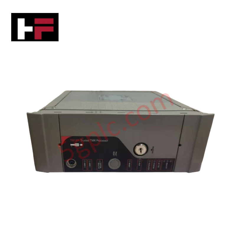
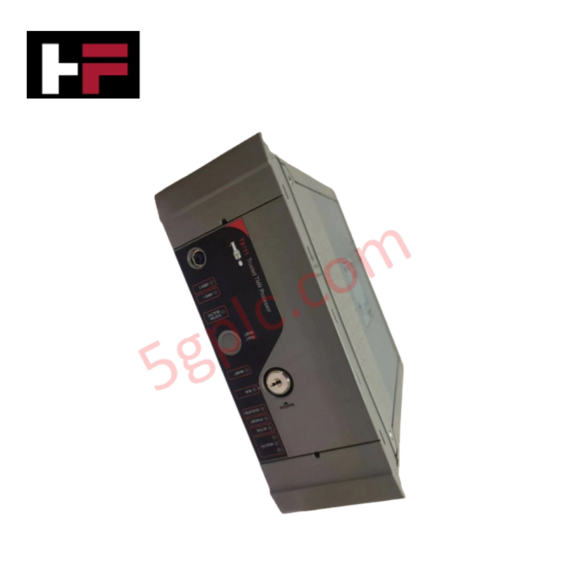
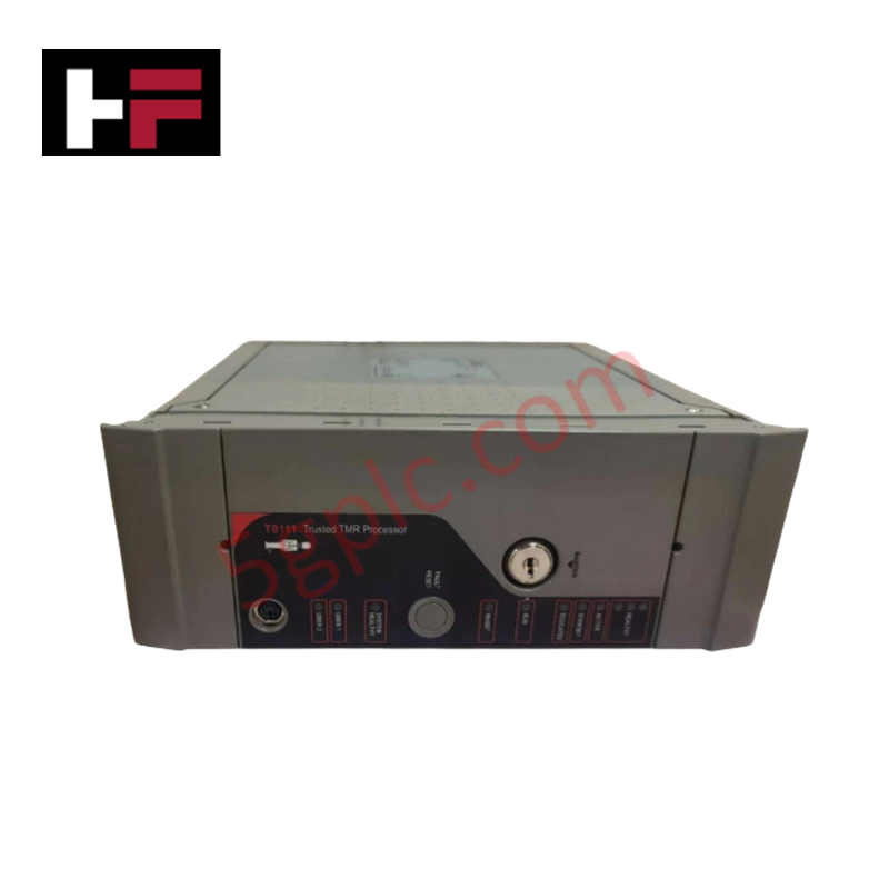
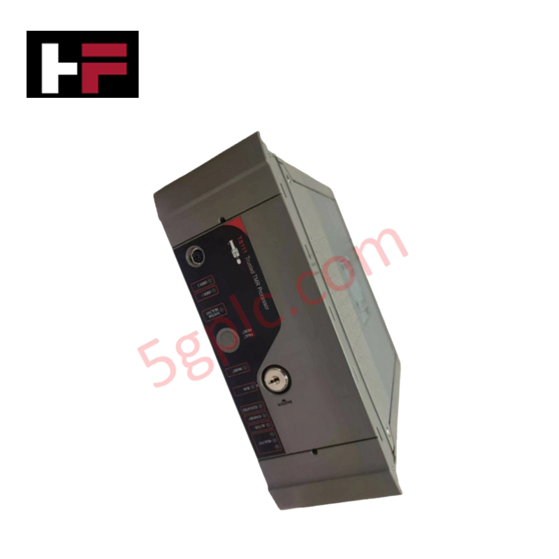
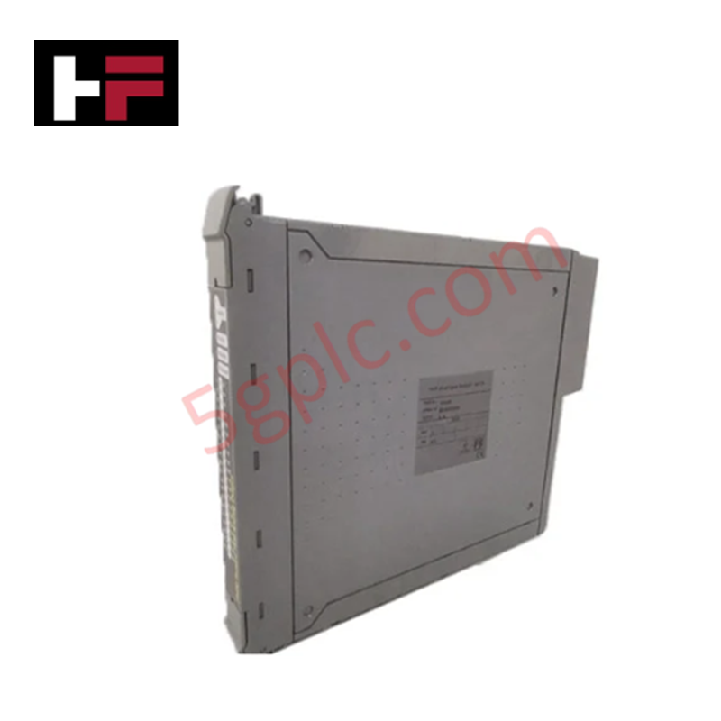
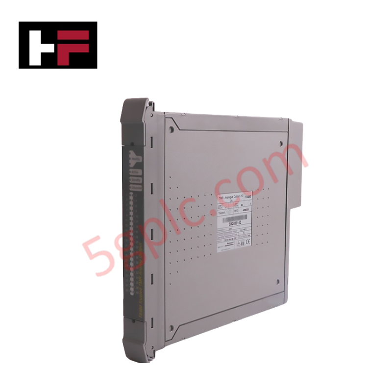
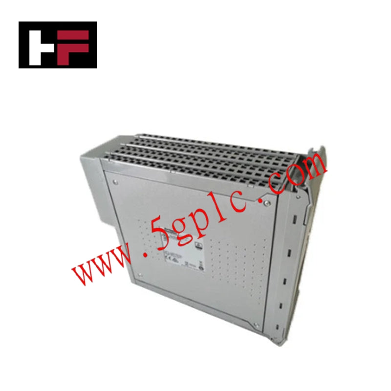
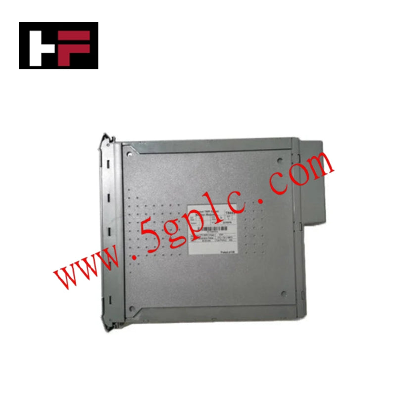
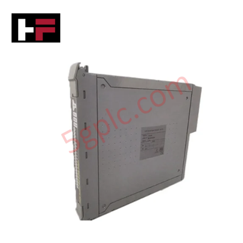
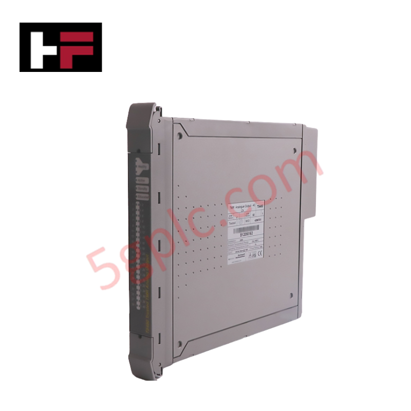
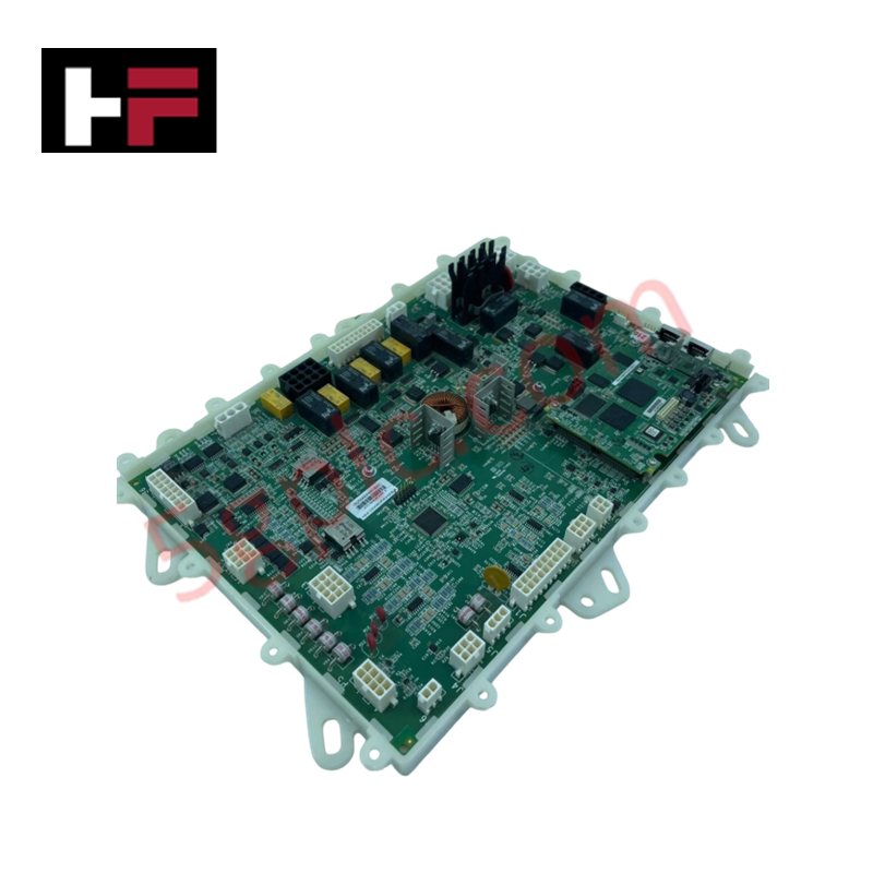
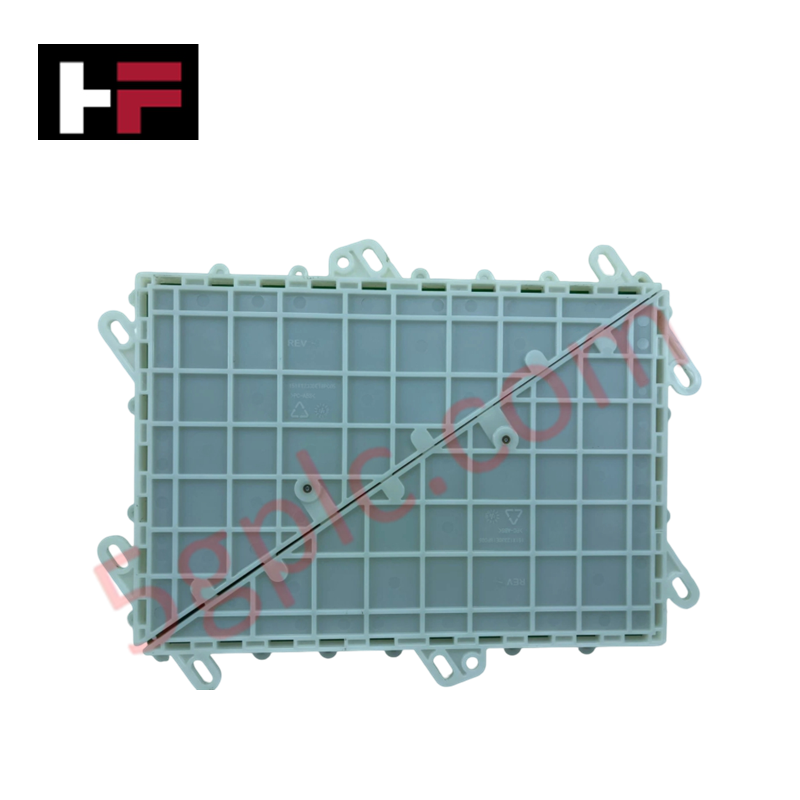
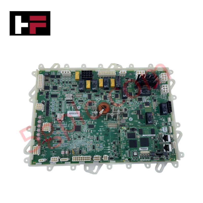
Configured for power distribution and auxiliary signal processing in GE Innovation Series drive platforms, the GE IS200AEPAH1BEB (IS200AEPA Circuit Board) provides direct physical/electrical execution.
Hardware Specifications
| Parameter | Specification |
|---|---|
| Model | IS200AEPAH1BEB |
| Brand | General Electric |
| Origin | USA |
| Weight | 0.85 kg |
| Dimensions | 280 x 210 x 40 mm |
| Operating Temp | 0 to 60 deg C |
| Power Consumption | 12 W |
| Board Series | Innovation Series Drive Control |
| Functional Acronym | AEPA |
| Revision Grade | Revision H1BEB |
| Board Coating | Conformal Coating |
| Interconnect Types | Multi-pin edge connectors, pluggable ribbon connectors |
Backplane Bus Communication Velocity and Firmware Flash Compatibility
The IS200AEPAH1BEB processes internal control signals across dedicated drive backplane assemblies. Onboard logic circuits and interface relays maintain high-speed signal routing to ensure backplane bus communication velocity across real-time motor control loops. The card provides native firmware flash compatibility across host GE Innovation Series rack configurations, allowing synchronized processing without manual firmware adjustments. Integrated test points and isolation barriers shield delicate low-voltage logic from power-stage transient surges.
Frequently Asked Questions
Q: How is the IS200AEPAH1BEB card physically secured within the drive assembly?
A: The card mounts directly into card cage guide slots and secures via retaining screws along its front edge bracket to maintain earth grounding and vibration stability.
Q: Are there onboard test points available for hardware diagnostics?
A: Yes, accessible surface test points (TP) allow technicians to measure internal power rail voltages and verify control signal state integrity directly.
Q: What precautions should be taken regarding static handling?
A: Always connect a grounded ESD wrist strap to the enclosure frame before touching card surfaces to protect onboard integrated circuits and surface-mount components.
Field Installation Guidelines
Isolate all main power feeds and control voltages supplying the drive rack prior to performing maintenance. Attach a calibrated ESD grounding strap to unpainted cabinet steel to prevent electrostatic discharge during module swap-out. Align the card edges with the enclosure mounting tracks, push firmly until the multi-pin backplane connectors fully seat, and torque retaining screws hand-tight. Ensure all ribbon cables and wiring harness plugs are locked into place before restoring system power.
Additional Information
- 100% Genuine Parts: All products are original and authentic, ensuring reliable industrial performance.
- 30-Day Refund Guarantee: Return any in-stock item within 30 days in original, unopened packaging for a full refund (excluding shipping and fees).
- 12-Month Warranty: Covers defects in materials or workmanship; excludes misuse, normal wear, or unauthorized modifications.
- Worldwide Shipping: We ship via USPS, UPS, FedEx, and DHL. Delivery times vary by country and may be subject to customs or import fees.
- Support & Contact: Technical and warranty assistance is available anytime. Contact us here: Contact.
- Purchase Guidance: Check product specifications and compatibility carefully before ordering to ensure proper application.


Tech & Buying Guide

Mastering VFD Braking Theory and Mechanical Brake Sequencing in Industrial Automation
In industrial automation, variable frequency drives (VFDs) regulate motor speed and torque across manufacturing plants and material handling systems. However, certain heavy-duty applications experience external loads that can rotate the motor shaft without an active command. For instance, gravity pulls loads downward in unanchored hoisting equipment. Therefore, engineers integrate mechanical brakes with VFD logic to maintain absolute safety and prevent structural damage or personnel injury during shutdowns.

Optimizing Tank Level Control Using Proportional Algorithms in PLC Systems
Industrial automation engineers frequently encounter liquid level regulation challenges across diverse process plants. Traditional ON-OFF control mechanisms often disrupt system stability due to abrupt actuator switching. Therefore, upgrading to closed-loop architectures like proportional control yields smoother responses. In a typical PLC environment, such as Siemens TIA Portal, engineers utilize closed-loop feedback to minimize process errors without requiring full PID complexity.

Understanding Why Your PLC Enters Stop Mode: Causes and Troubleshooting
In industrial automation, programmable logic controllers (PLCs) serve as the core intelligence of modern factory automation and distributed control systems (DCS). Understanding how a PLC transitions between modes is vital for maintenance engineers. Typically, a PLC operates across four primary modes: Run, Stop, Start-Up, and Hold. When power is applied, the system immediately boots into Stop mode before initiating the Start-Up sequence. If the controller encounters a critical error during execution, it automatically reverts to Stop mode to prevent equipment damage. Therefore, monitoring these state transitions helps technicians maintain high system availability.