
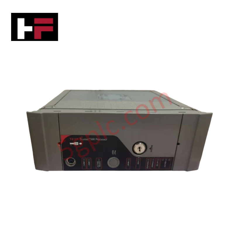
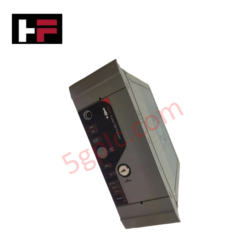
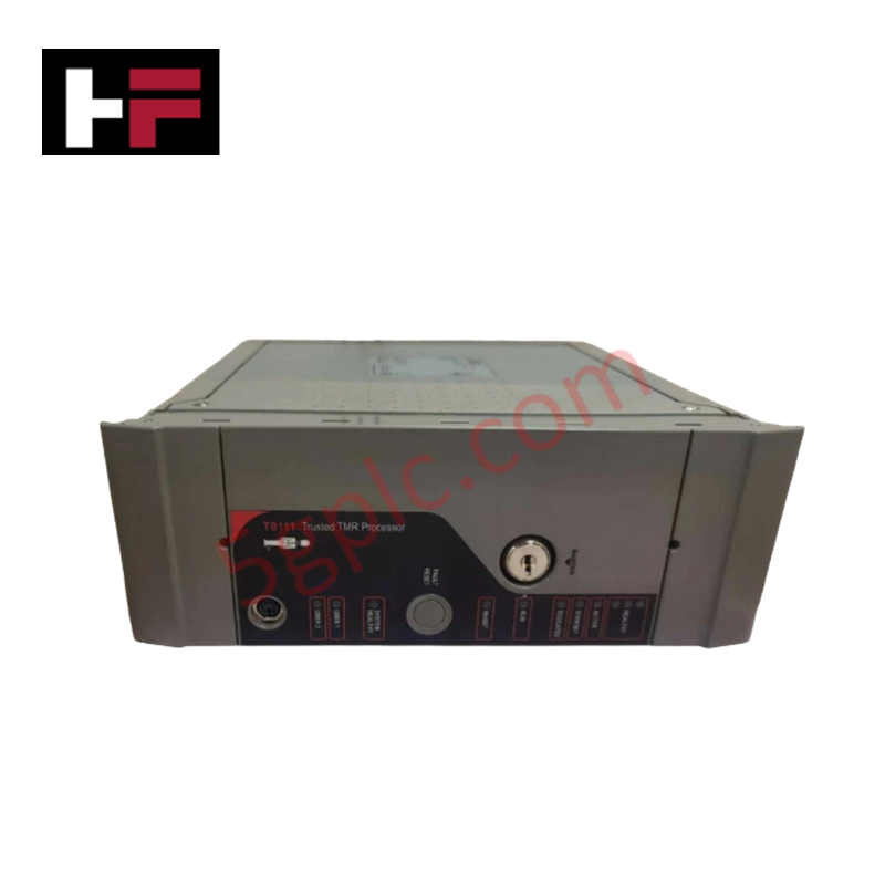
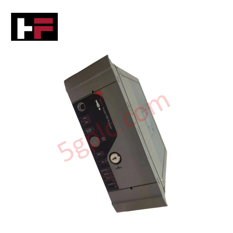
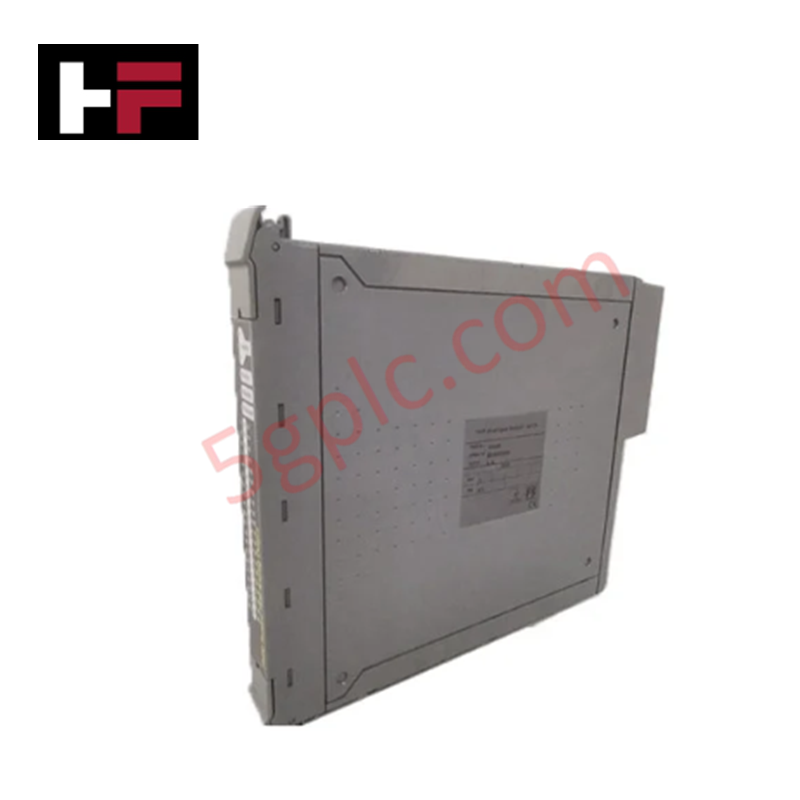
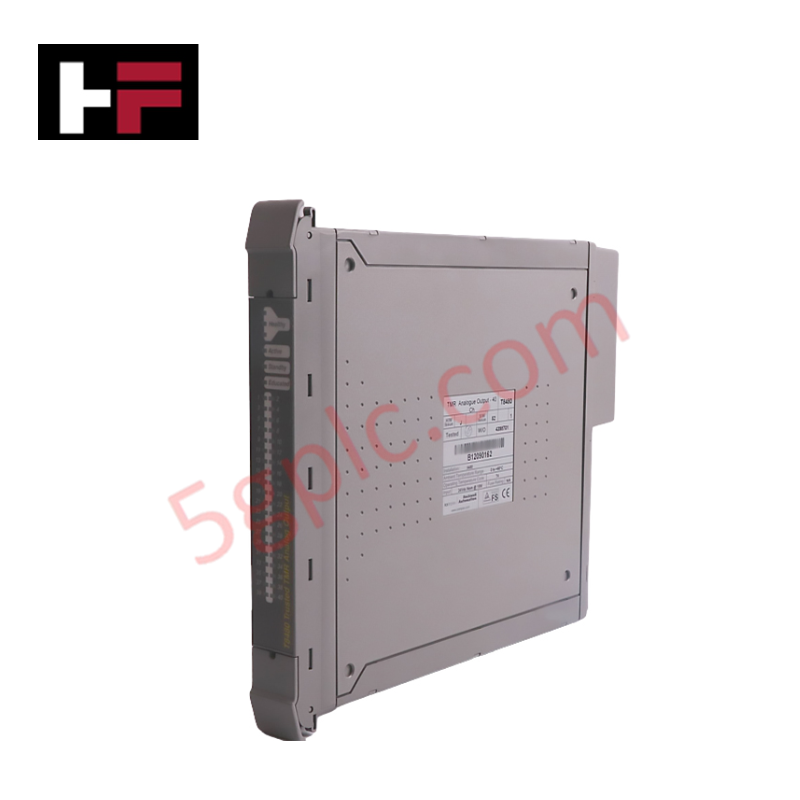
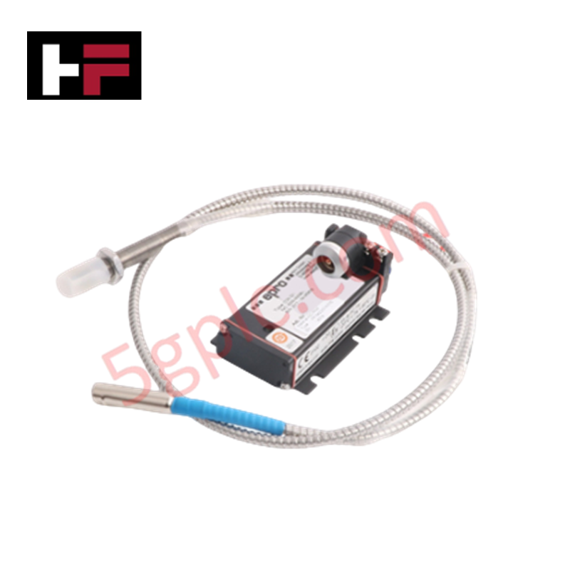
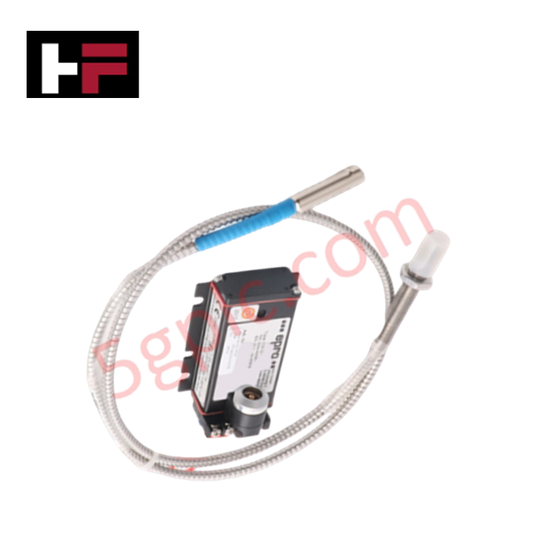
Product Details
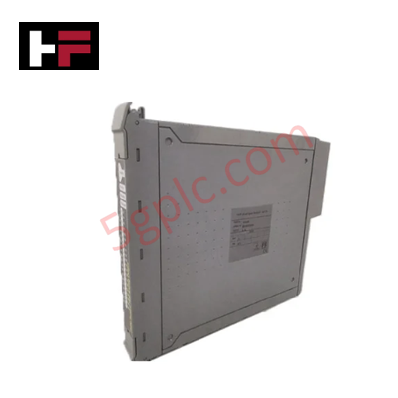
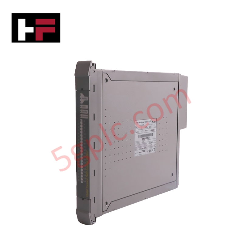
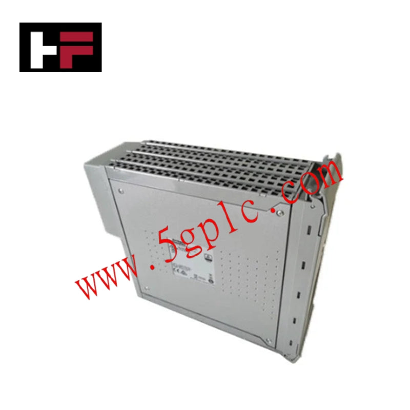
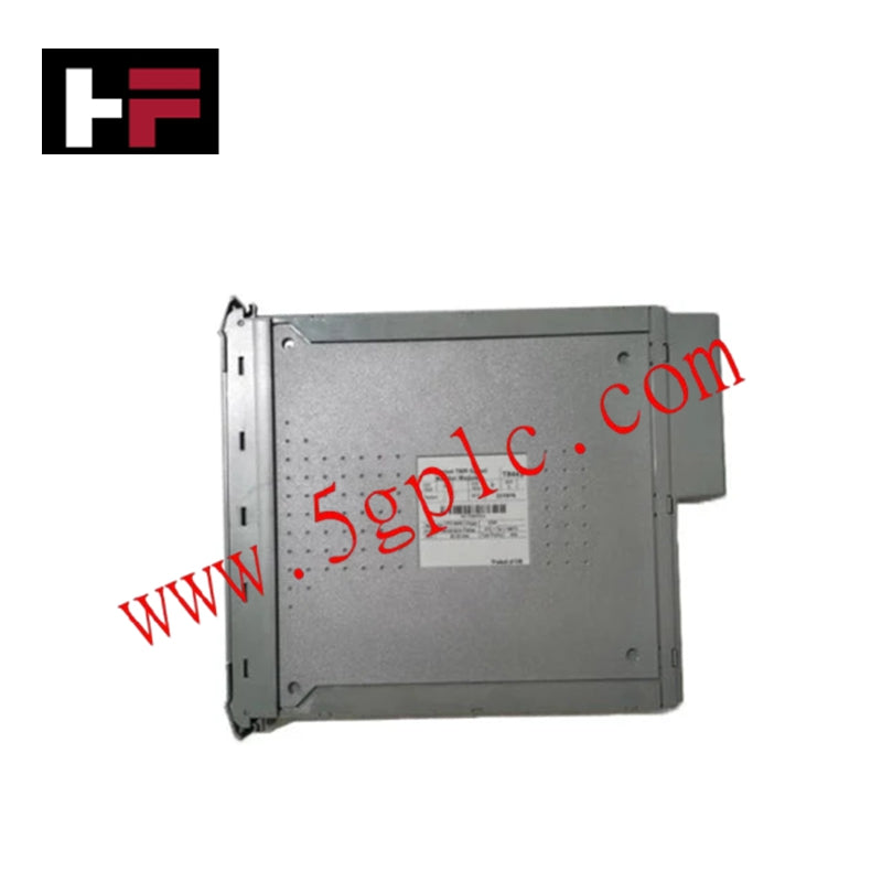
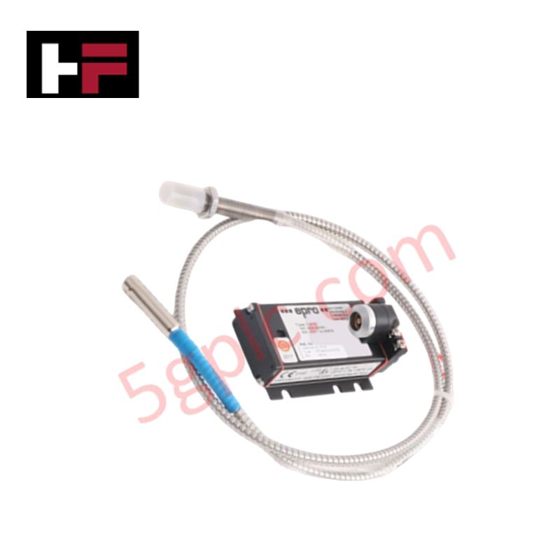
Configured for precision vibration velocity and displacement monitoring in rotating machinery, the Emerson Epro PR6424/010-010 (PR6424/010-010 Eddy Current Sensor) provides direct physical signal execution. This transducer operates by converting mechanical shaft oscillations into proportional electrical signals, providing high-speed diagnostic data to support real-time machinery condition evaluation.
Hardware Specifications
| Parameter | Specification |
|---|---|
| Model | PR6424/010-010 |
| Brand | Emerson (Epro) |
| Origin | Subject to certificate of origin |
| Weight | Not specified |
| Dimensions | 16 mm sensor diameter |
| Operating Temp | -30 deg C to +100 deg C |
| Power Consumption | 18-30 VDC |
| Measurement Range | +/- 2 mm/s (velocity) / +/- 20 um (displacement) |
| Sensitivity | 20 mV/mm/s +/- 5% |
| Protection Class | IP67 |
Rotor Dynamics and Gap Voltage Validation
The measurement performance of the Emerson Epro PR6424/010-010 relies on maintaining a precise gap between the probe tip and the rotating shaft surface. Validation of the gap voltage is required during the static baseline phase to ensure the system output is centered within the linear transducer range. In dynamic applications, rotor dynamics necessitate that the sensor mounting bracket be stiff enough to avoid introducing mechanical resonance into the measurement. Additionally, cross-talk suppression must be enforced by ensuring adequate spatial separation from adjacent proximity probes to prevent interference between synchronized carrier signals.
Frequently Asked Questions
Q: Is this sensor suitable for direct replacement of units using different output signal types?
A: No, the output signal format (4-20 mA or voltage) is configured at the device level. Ensure the monitoring system input card matches the specific output configuration of the PR6424/010-010.
Q: Does the IP67 protection rating allow for continuous submersion?
A: The IP67 rating denotes that the sensor is dust-tight and resistant to temporary water immersion. It is not designed for continuous underwater service in high-pressure hydraulic applications.
Field Installation Guidelines
- Mounting: Install the sensor perpendicular to the target surface using a rigid mounting bracket. Tighten the M12x1 connection ensuring proper O-ring seating to maintain the IP67 ingress protection rating.
- Grounding: Route the sensor wiring through dedicated conduit separate from high-power AC lines to prevent induced noise. Terminate all shields at a single, verified instrument ground point.
- Cabling: Utilize shielded twisted-pair cabling for the connection between the sensor and the monitoring interface. Avoid exceeding the maximum cable length specified for the loop resistance limits.
- Target Verification: Ensure the target shaft surface is free of physical damage, non-conductive coatings, or deep scratches that could distort the eddy current field.
Additional Information
- 100% Genuine Parts: All products are original and authentic, ensuring reliable industrial performance.
- 30-Day Refund Guarantee: Return any in-stock item within 30 days in original, unopened packaging for a full refund (excluding shipping and fees).
- 12-Month Warranty: Covers defects in materials or workmanship; excludes misuse, normal wear, or unauthorized modifications.
- Worldwide Shipping: We ship via USPS, UPS, FedEx, and DHL. Delivery times vary by country and may be subject to customs or import fees.
- Support & Contact: Technical and warranty assistance is available anytime. Contact us here: Contact.
- Purchase Guidance: Check product specifications and compatibility carefully before ordering to ensure proper application.

Tech & Buying Guide

Mastering VFD Braking Theory and Mechanical Brake Sequencing in Industrial Automation
In industrial automation, variable frequency drives (VFDs) regulate motor speed and torque across manufacturing plants and material handling systems. However, certain heavy-duty applications experience external loads that can rotate the motor shaft without an active command. For instance, gravity pulls loads downward in unanchored hoisting equipment. Therefore, engineers integrate mechanical brakes with VFD logic to maintain absolute safety and prevent structural damage or personnel injury during shutdowns.

Optimizing Tank Level Control Using Proportional Algorithms in PLC Systems
Industrial automation engineers frequently encounter liquid level regulation challenges across diverse process plants. Traditional ON-OFF control mechanisms often disrupt system stability due to abrupt actuator switching. Therefore, upgrading to closed-loop architectures like proportional control yields smoother responses. In a typical PLC environment, such as Siemens TIA Portal, engineers utilize closed-loop feedback to minimize process errors without requiring full PID complexity.

Understanding Why Your PLC Enters Stop Mode: Causes and Troubleshooting
In industrial automation, programmable logic controllers (PLCs) serve as the core intelligence of modern factory automation and distributed control systems (DCS). Understanding how a PLC transitions between modes is vital for maintenance engineers. Typically, a PLC operates across four primary modes: Run, Stop, Start-Up, and Hold. When power is applied, the system immediately boots into Stop mode before initiating the Start-Up sequence. If the controller encounters a critical error during execution, it automatically reverts to Stop mode to prevent equipment damage. Therefore, monitoring these state transitions helps technicians maintain high system availability.