
Product Details
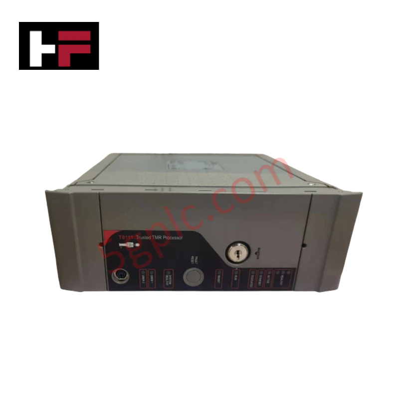
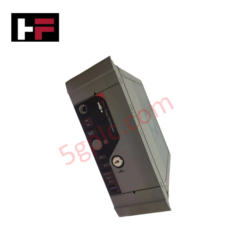
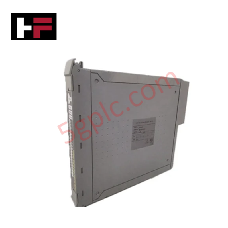
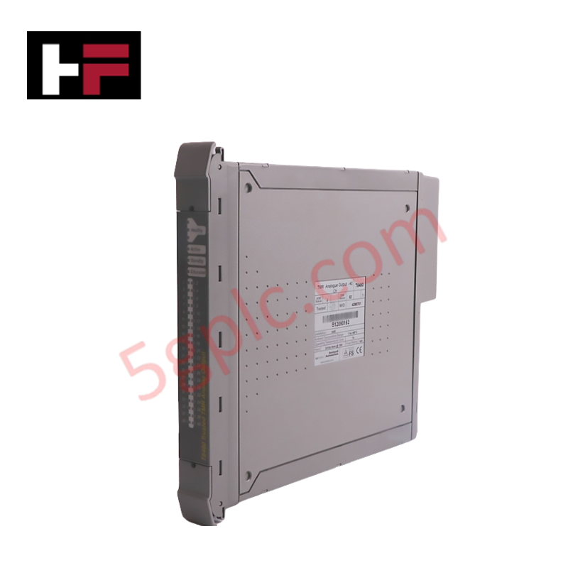
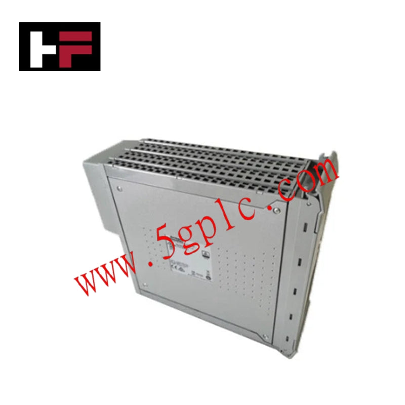
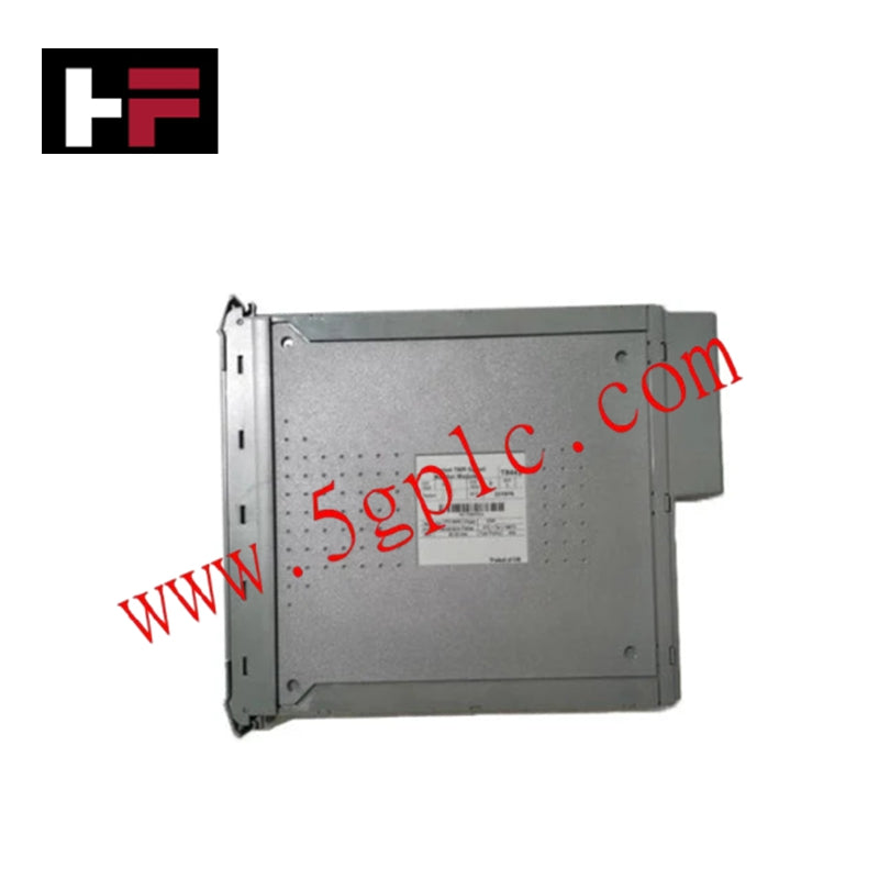
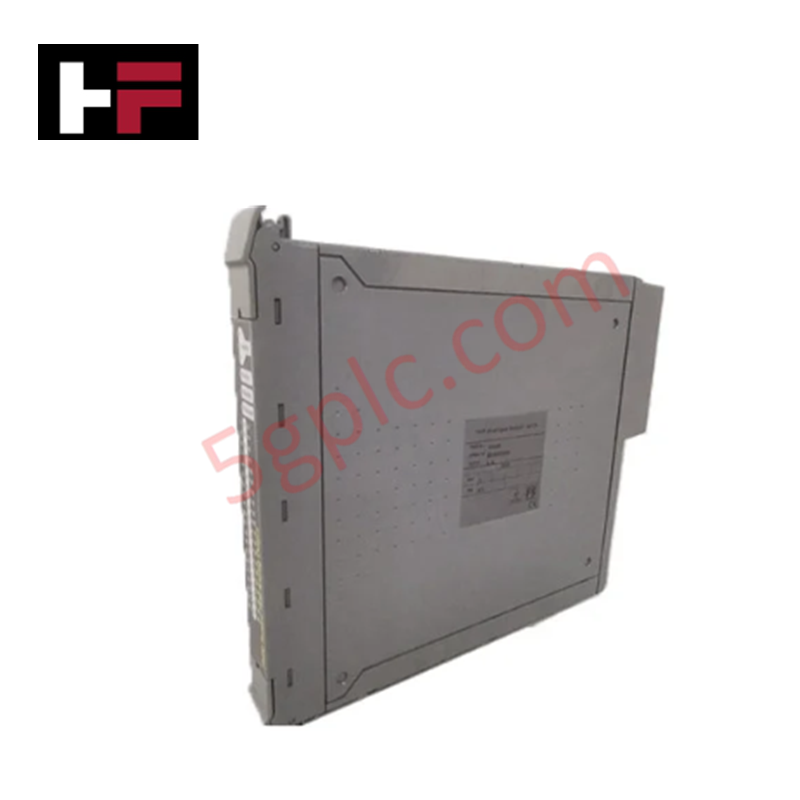
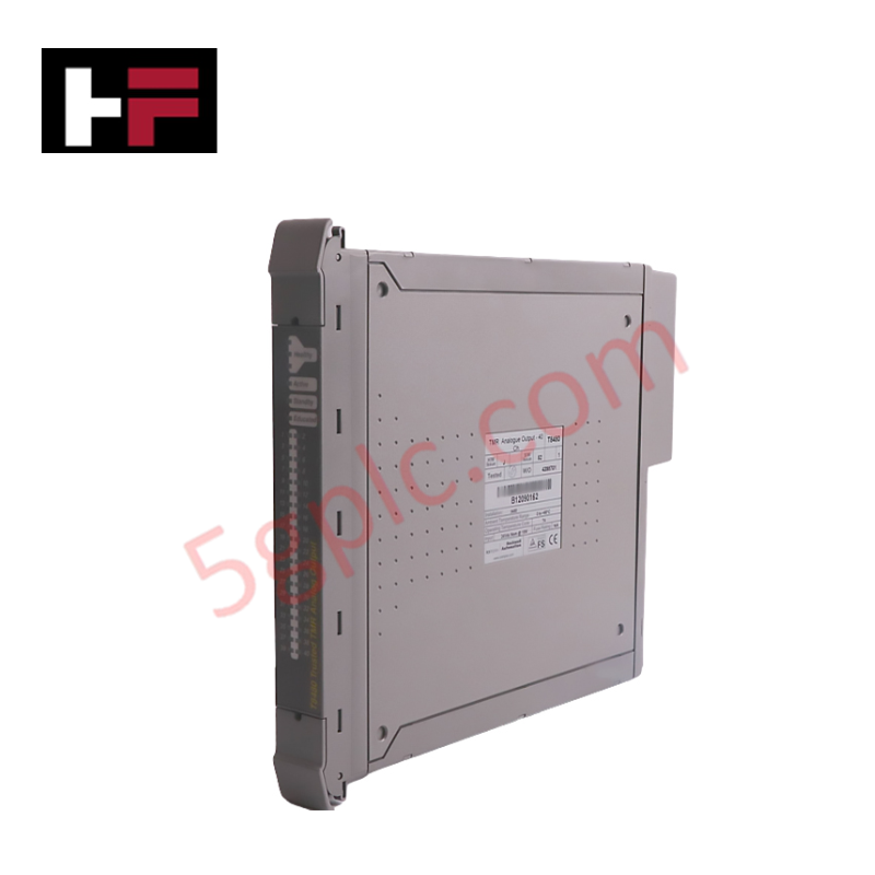
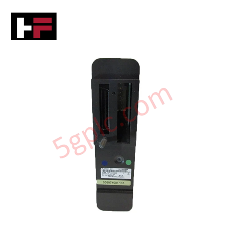
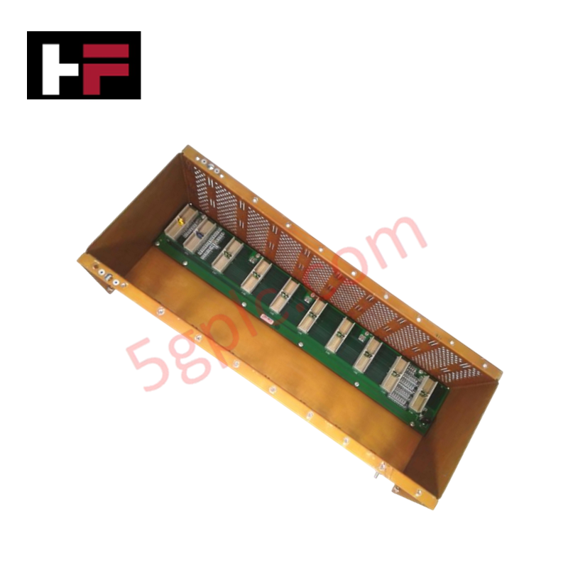
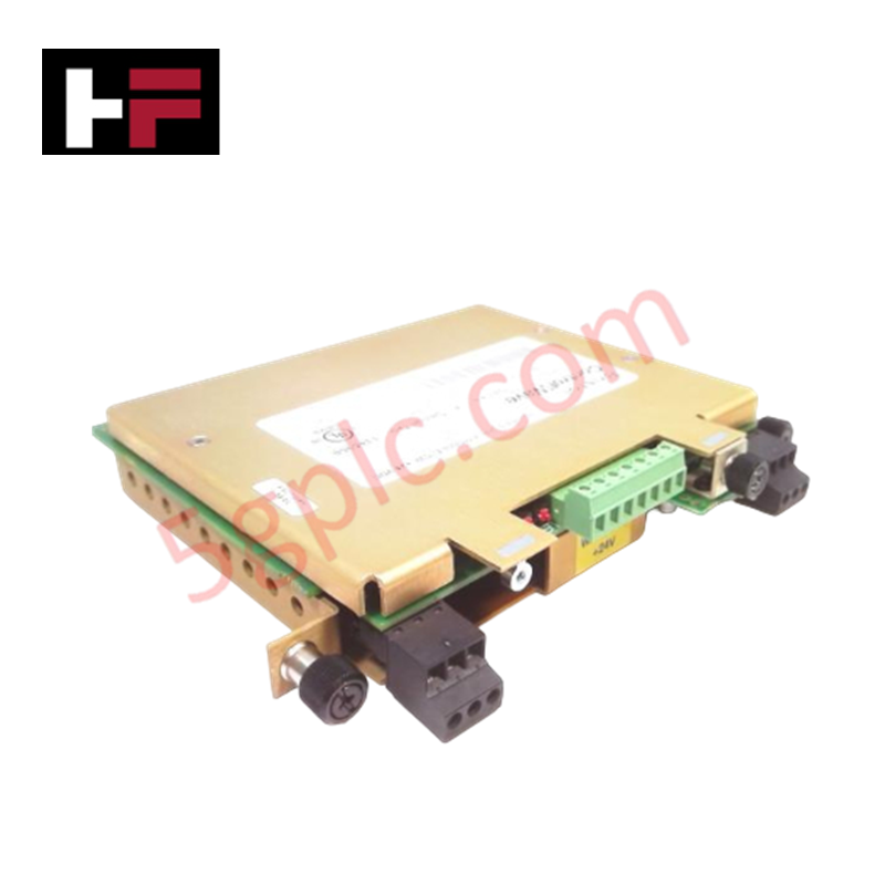
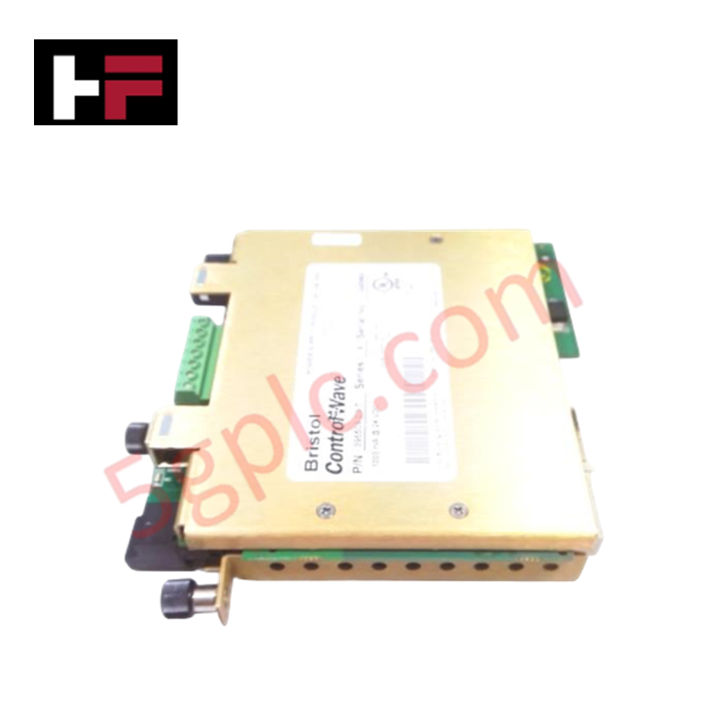
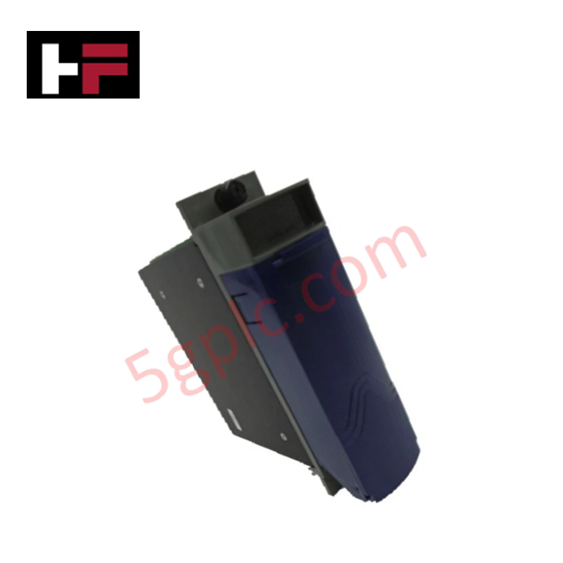
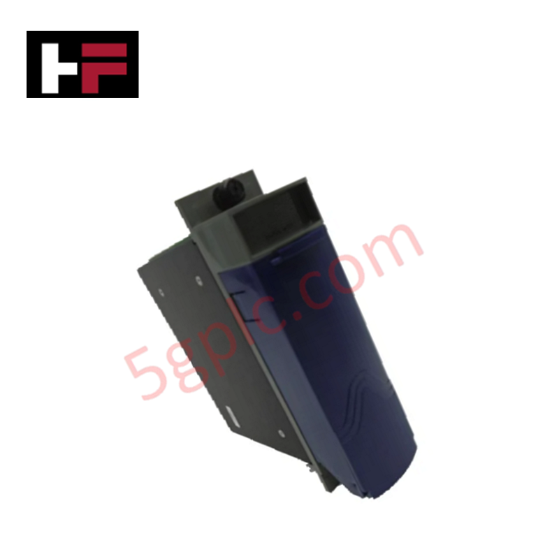
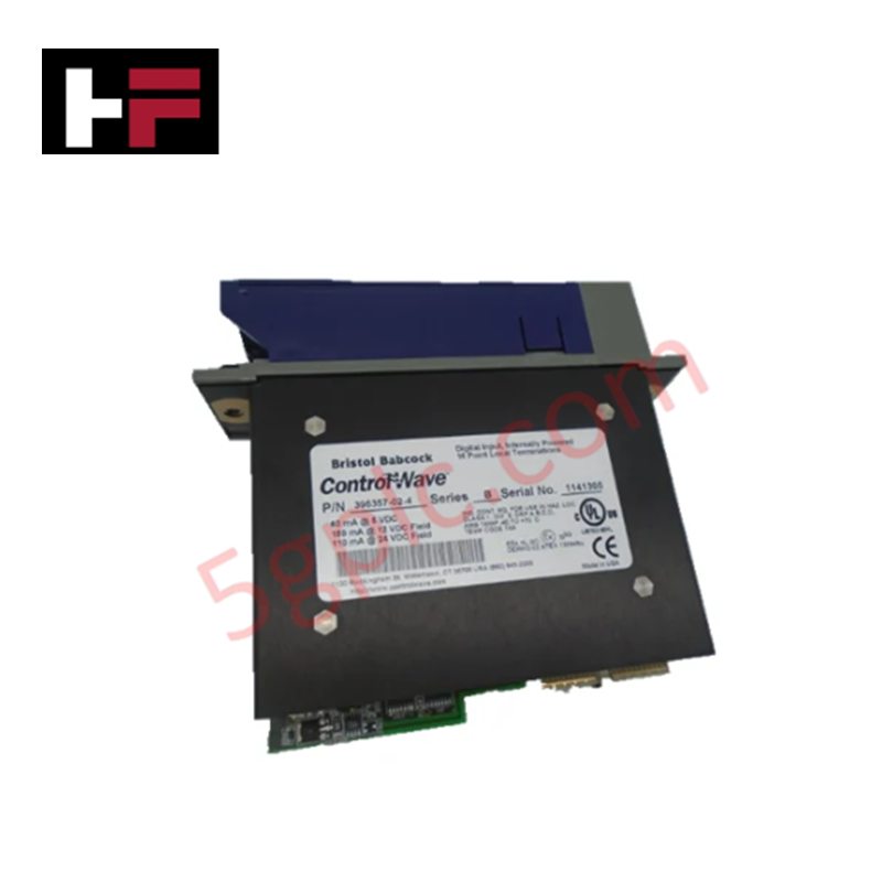
The Emerson 15B10937G1, also cataloged as the 15B10937G1 Industrial Control Board, operates as a dedicated hardware component for direct logic signal routing and processing execution within Emerson distributed control platforms. It mounts directly into backplane enclosures to establish high-speed bus connectivity across system input and output channels.
Hardware Specifications
| Parameter | Specification |
|---|---|
| Model | 15B10937G1 |
| Brand | Emerson |
| Base Model | 15B10937G1 |
| Origin | USA |
| Weight | 0.2 lbs (0.09 kg) |
| Dimensions | 2.5 cm x 27.9 cm x 25.4 cm |
| Operating Temp | Standard enclosure rating |
| Power Consumption | Backplane logic bus powered |
| Board Type | Industrial Control Board |
FOUNDATION Fieldbus / Profibus PA Connectivity and Channel Isolation
The 15B10937G1 control board incorporates galvanically isolated signal interface paths to maintain baseline stability across high-density field networks. Internal isolation barriers protect processing logic against voltage spikes and common-mode line noise. This physical separation prevents ground loop propagation when interfacing directly with field junction units and instruments operating over FOUNDATION Fieldbus / Profibus PA connectivity networks or standard analog wiring.
Frequently Asked Questions
Q: What power interface is required to energize the 15B10937G1 control board?
A: The board draws operating potential directly from the rack backplane power rails upon physical insertion into the slot.
Q: Are there physical keying mechanisms to prevent improper insertion?
A: Standard rack slots utilize physical guide rails and edge connector keying to ensure correct module alignment during cabinet assembly.
Q: What precautions must be observed regarding electrostatic discharge during installation?
A: Service personnel must wear grounded wrist straps and handle the board strictly by its mechanical edges to protect onboard CMOS components from static damage.
Field Installation Guidelines
- Disconnect backplane main power before inserting or removing the circuit board from the subrack chassis.
- Align the top and bottom board edges with the enclosure card guides prior to sliding the unit into position.
- Push the board steadily inward until the card-edge connectors seat fully into the backplane mating receptacle.
- Secure panel mounting hardware or card retention screws to maintain continuous mechanical ground bonding.
- Inspect field wiring shields at terminal blocks to confirm single-point earthing according to site earthing specifications.
Additional Information
- 100% Genuine Parts: All products are original and authentic, ensuring reliable industrial performance.
- 30-Day Refund Guarantee: Return any in-stock item within 30 days in original, unopened packaging for a full refund (excluding shipping and fees).
- 12-Month Warranty: Covers defects in materials or workmanship; excludes misuse, normal wear, or unauthorized modifications.
- Worldwide Shipping: We ship via USPS, UPS, FedEx, and DHL. Delivery times vary by country and may be subject to customs or import fees.
- Support & Contact: Technical and warranty assistance is available anytime. Contact us here: Contact.
- Purchase Guidance: Check product specifications and compatibility carefully before ordering to ensure proper application.

Tech & Buying Guide

Optimizing Tank Level Control Using Proportional Algorithms in PLC Systems
Industrial automation engineers frequently encounter liquid level regulation challenges across diverse process plants. Traditional ON-OFF control mechanisms often disrupt system stability due to abrupt actuator switching. Therefore, upgrading to closed-loop architectures like proportional control yields smoother responses. In a typical PLC environment, such as Siemens TIA Portal, engineers utilize closed-loop feedback to minimize process errors without requiring full PID complexity.

Understanding Why Your PLC Enters Stop Mode: Causes and Troubleshooting
In industrial automation, programmable logic controllers (PLCs) serve as the core intelligence of modern factory automation and distributed control systems (DCS). Understanding how a PLC transitions between modes is vital for maintenance engineers. Typically, a PLC operates across four primary modes: Run, Stop, Start-Up, and Hold. When power is applied, the system immediately boots into Stop mode before initiating the Start-Up sequence. If the controller encounters a critical error during execution, it automatically reverts to Stop mode to prevent equipment damage. Therefore, monitoring these state transitions helps technicians maintain high system availability.

Comprehensive Guide to Servo Motor Drive Control Techniques in Industrial Automation
Precision motion control systems drive high-throughput manufacturing across modern industrial automation environments. Unlike standard induction motors running on basic variable frequency drives, servo motor systems deliver sub-millimeter positioning accuracy and fast dynamic response.