












Product Details
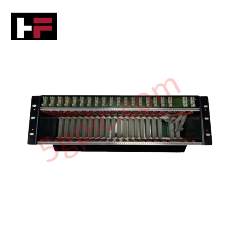
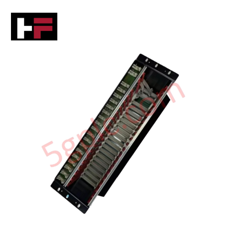
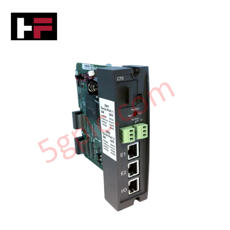
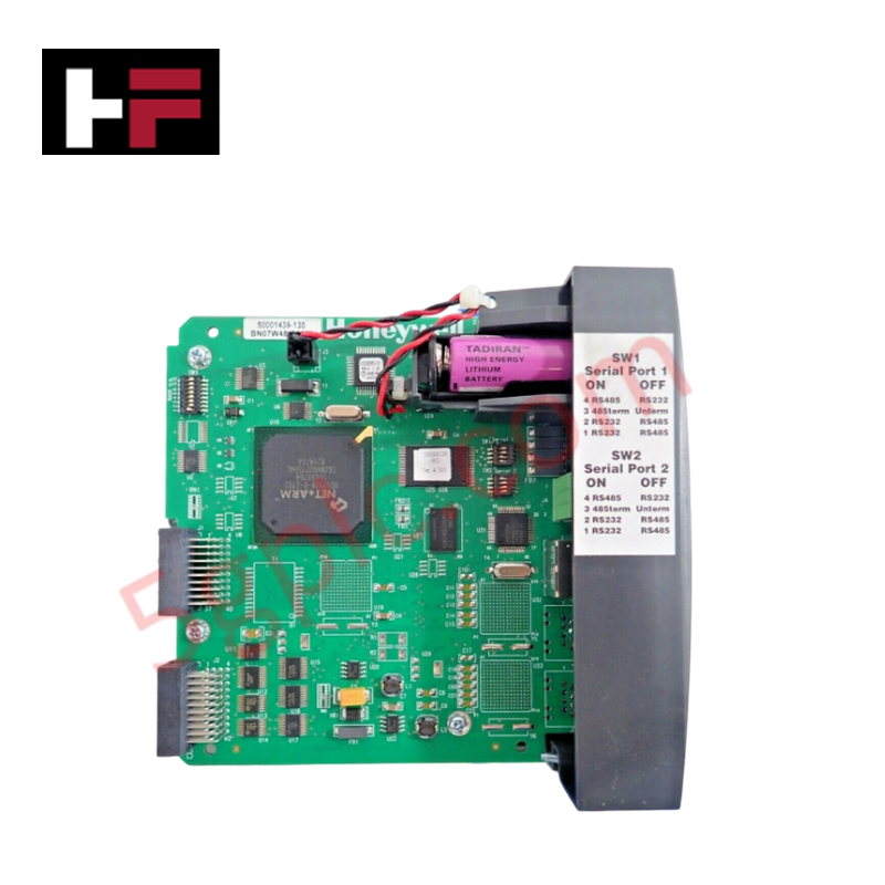
The Honeywell FS-CPCHAS-0002, also cataloged as the FS-CPCHAS-0002 Control Processor Chassis, operates as a dedicated hardware component for multi-processor physical housing, internal power allocation, and inter-module backplane signal routing within Honeywell Safety Manager and Experion PKS platforms.
Hardware Specifications
| Parameter | Specification |
|---|---|
| Model | FS-CPCHAS-0002 |
| Brand | Honeywell |
| Origin | USA |
| Weight | 5.8 kg |
| Dimensions | 280 x 482.6 x 177 mm |
| Operating Temp | 0 to +50 deg C |
| Power Consumption | Passive chassis backplane (Internal bus powered via 24 VDC feeder) |
| Power Supply Input | 24 VDC |
| Communication | RS-485 backplane interface |
| Storage Temperature | -40 to +70 deg C |
| Mounting Options | 19-inch rack mount or panel mount |
| Safety Compliance | Designed for IEC 61508 SIL-compliant systems |
Process Control & DCS Backplane Characteristics
The FS-CPCHAS-0002 assembly features channel-to-channel isolation across backplane bus lines to prevent common-mode electrical faults from impairing primary logic processing units. Onboard copper tracks establish deterministic RS-485 serial communications between controller sub-assemblies while shielding high-speed data buses from ambient noise interference. The power backplane distributes 24 VDC directly to inserted processing modules, ensuring regulated voltage delivery across high-density I/O configurations without signal degradation in 4-20 mA HART loop protocol subsystem networks.
Frequently Asked Questions
Q: What are the backplane bus current distribution limits on the FS-CPCHAS-0002 chassis?
A: The passive backplane copper trace network is rated to route a primary 24 VDC supply directly to inserted controller cards, supporting max backplane bus current capacity determined by the upstream chassis power supply unit.
Q: Can controller modules housed within the FS-CPCHAS-0002 chassis be hot-swapped during operation?
A: Hot-swapping individual processor modules within the chassis backplane is permitted in redundant controller architectures, provided static discharge prevention protocols are followed and the partner card holds active control.
Field Installation Guidelines
- Mechanical Mounting: Secure the chassis into a standard 19-inch equipment rack or onto a panel backplate using four M6 mounting screws. Ensure the frame sits level to avoid mechanical stress on internal backplane headers.
- Grounding & Earthing: Attach a heavy-gauge copper earthing strap directly from the dedicated chassis ground stud to the central cabinet earth bus bar to ensure low-impedance transient protection.
- Power Wiring Connections: Terminate incoming 24 VDC primary power leads directly to the chassis supply terminals using stranded copper conductors. Tighten terminal screws to manufacturer torque limits.
- Thermal Ventilation: Maintain at least 50 mm of vertical ventilation space above and below the chassis assembly inside the cabinet to permit free convective airflow within the 0 to +50 deg C operating window.
Additional Information
- 100% Genuine Parts: All products are original and authentic, ensuring reliable industrial performance.
- 30-Day Refund Guarantee: Return any in-stock item within 30 days in original, unopened packaging for a full refund (excluding shipping and fees).
- 12-Month Warranty: Covers defects in materials or workmanship; excludes misuse, normal wear, or unauthorized modifications.
- Worldwide Shipping: We ship via USPS, UPS, FedEx, and DHL. Delivery times vary by country and may be subject to customs or import fees.
- Support & Contact: Technical and warranty assistance is available anytime. Contact us here: Contact.
- Purchase Guidance: Check product specifications and compatibility carefully before ordering to ensure proper application.






Tech & Buying Guide
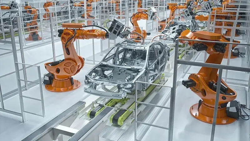
Safety Relays in Industrial Automation: Fundamentals, Design Standards, and Fail-Safe Architecture
Safety relays form the bedrock of functional safety in modern factory automation, preventing catastrophic equipment failure and protecting plant personnel. While standard electromechanical relays handle basic load switching, they lack the redundant diagnostics required for high-risk industrial environments. Modern industrial automation platforms—including programmable logic controllers (PLCs) and distributed control systems (DCS)—rely on specialized safety relays to monitor field devices and isolate hazards instantly.

Voice-Activated Industrial Automation: Integrating Speech Control into PLC and DCS Architectures
Industrial automation integrates speech recognition, IIoT protocols, and NLP with PLCs and DCS to streamline operations. By leveraging advanced edge computing, engineers enable real-time, hands-free control—allowing personnel to manage smart factory processes safely away from hazardous equipment.
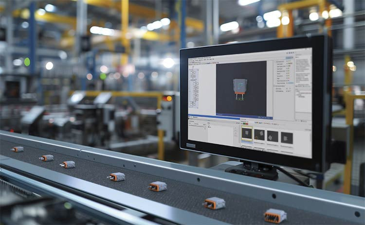
Modern Industrial Automation: Transforming Safety and Efficiency in Mining Operations
Industrial automation has evolved from a simple manufacturing tool into the operational backbone of high-risk sectors. Modern mining operations increasingly rely on advanced control systems, programmable logic controllers (PLCs), distributed control systems (DCS), and artificial intelligence to address deep-underground hazards. By replacing manual labor in high-risk zones, factory automation technologies protect personnel while significantly boosting operational throughput.