












Product Details
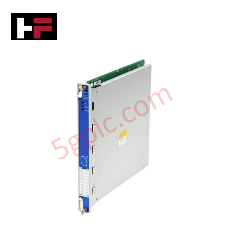
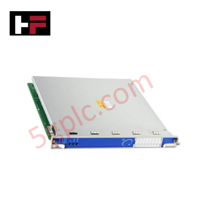
The Emerson A6824, also cataloged as the A6824 Modbus and Rack Interface Modules, operates as a dedicated hardware component for bidirectional Modbus serial telemetry and rack bus data extraction within CSI 6500 Machinery Health Monitoring System platforms. The module establishes physical layer serial data transmission and backplane interface control, connecting machinery vibration monitors directly to upper-tier control networks.
Hardware Specifications
| Parameter | Specification |
|---|---|
| Model | A6824 |
| Brand | Emerson |
| Origin | USA |
| Weight | 0.24 kg |
| Dimensions | 3.1 cm x 19 cm x 12.8 cm |
| Operating Temp | Extended industrial range |
| Power Consumption | Backplane powered via CSI 6500 rack bus |
| Module Type | Modbus & Rack Interface Module |
| Series | CSI 6500 |
| System Compatibility | DCS, CSI 6500 System |
| Communication Interface | Modbus RTU / Ethernet router service |
| Hardware Status | Discontinued legacy module |
4-20 mA HART Loop Protocol and Channel Isolation
The rack interface module incorporates channel-to-channel isolation protocols across its internal communications bus to prevent ground loops between the machinery monitoring chassis and external controllers. Designed for process control networks utilizing 4-20 mA HART loop protocol architectures and DCS networks, the interface isolates digital Modbus telemetry from field electrical noise. Internal signal paths include temperature-stabilized reference circuits that maintain cold junction compensation integrity across connected analog measurement channels during ambient panel temperature shifts.
Frequently Asked Questions
Q: Does the A6824 module support hot-swapping inside an active CSI 6500 rack frame?
A: Module removal or insertion requires verifying rack backplane power distribution and communication lock states to prevent serial bus interruption to downstream DCS controllers.
Q: How does the A6824 handle channel-to-channel isolation between internal rack signals and the external Modbus loop?
A: Galvanic isolation barriers built into the communication interface shield internal rack processing buses from external field line transients and ground potential differences.
Q: What is the primary power source required to operate the A6824 interface module?
A: Power is drawn directly from the internal CSI 6500 rack backplane bus rails, eliminating the need for an external direct DC power connection to the front panel.
Field Installation Guidelines
- Power down the designated rack slot or confirm system redundancy protocol before inserting the module into the CSI 6500 frame.
- Align the module circuit board with the upper and lower guide rails of the CSI 6500 chassis slot.
- Slide the card inward until the backplane edge connectors engage fully with the rack bus socket.
- Tighten the top and bottom front panel captive screws to establish mechanical chassis grounding and secure physical mounting.
- Connect the shielded Modbus communication cable to the designated RJ-45 or serial interface port.
- Terminate cable shields at the single-point cabinet ground bar to prevent noise pickup on serial communication lines.
Additional Information
- 100% Genuine Parts: All products are original and authentic, ensuring reliable industrial performance.
- 30-Day Refund Guarantee: Return any in-stock item within 30 days in original, unopened packaging for a full refund (excluding shipping and fees).
- 12-Month Warranty: Covers defects in materials or workmanship; excludes misuse, normal wear, or unauthorized modifications.
- Worldwide Shipping: We ship via USPS, UPS, FedEx, and DHL. Delivery times vary by country and may be subject to customs or import fees.
- Support & Contact: Technical and warranty assistance is available anytime. Contact us here: Contact.
- Purchase Guidance: Check product specifications and compatibility carefully before ordering to ensure proper application.




Tech & Buying Guide

Understanding PLC Digital Output Types: Relay, Transistor, and Triac Explained
Programmable Logic Controllers (PLCs) form the backbone of modern industrial automation systems. They interface directly with field devices such as solenoid valves, indicator lights, motor starters, and interposing relays. Selecting the correct digital output module ensures high system availability and long hardware service life.

Understanding VFD Mechanical Brake Logic and Control in Industrial Automation
Variable Frequency Drives (VFDs) play a crucial role in modern industrial automation by controlling motor speed, torque, and acceleration. However, high-inertia loads and vertical lifting systems require precise mechanical braking logic to ensure operational safety and prevent equipment damage.

Why Programmable Logic Controllers Drop into Stop Mode: An Expert Analysis
Industrial automation systems rely heavily on Programmable Logic Controllers (PLCs) to maintain uninterrupted production. When a PLC unexpectedly shifts from Run to Stop mode, whole manufacturing lines stall.
As control systems evolve across modern factory automation, understanding the root causes of these interruptions helps engineers minimize costly downtime. This technical guide breaks down why PLCs trip into Stop mode and provides practical strategies to mitigate system faults.