










Product Details
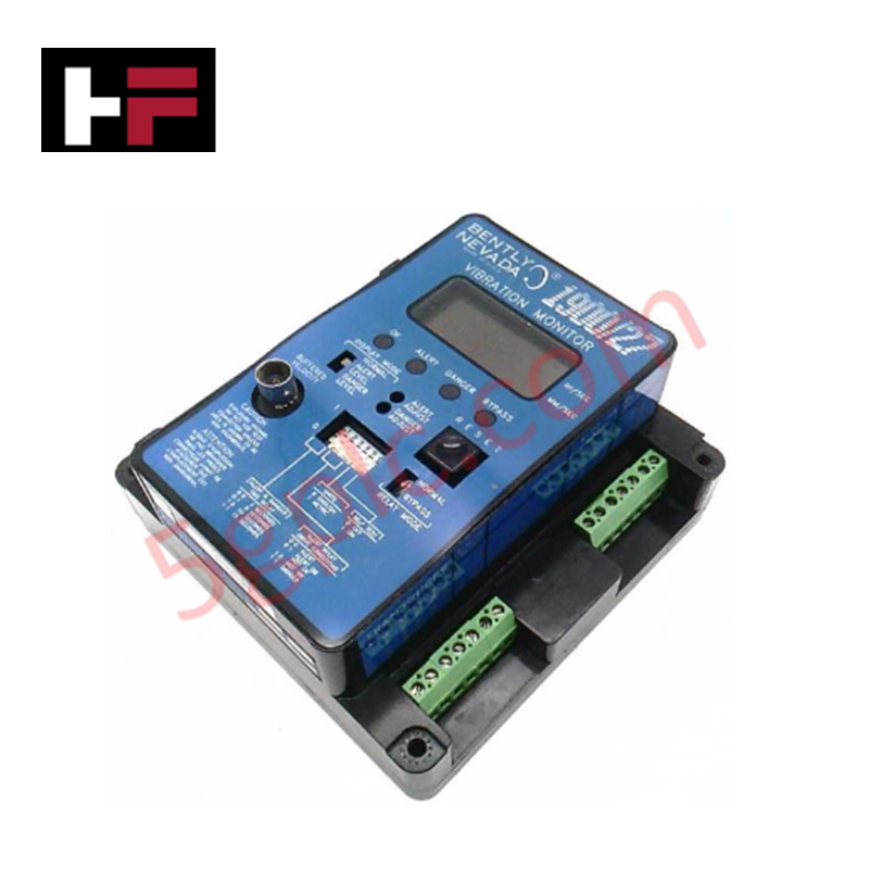
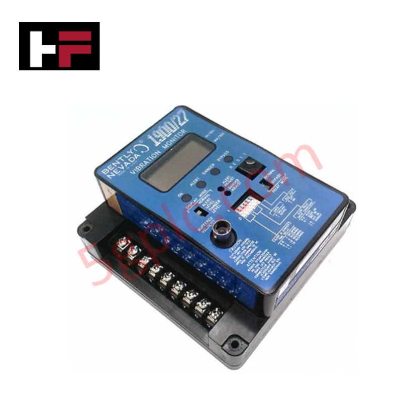
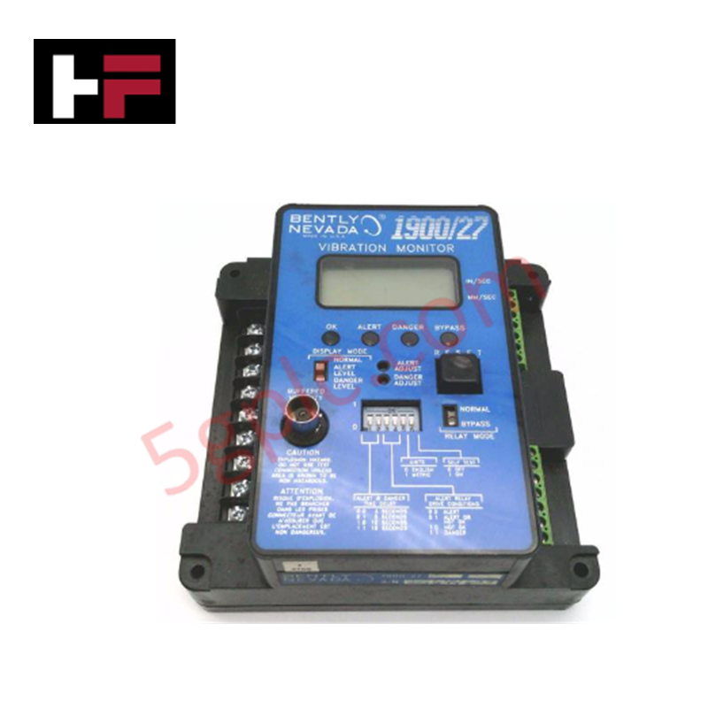
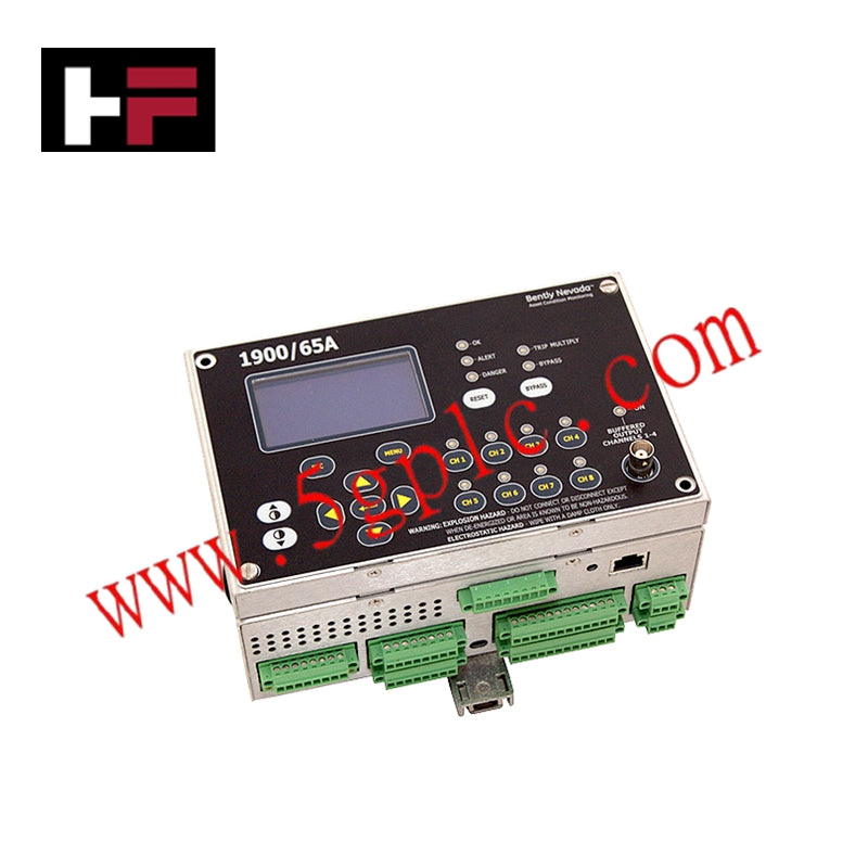
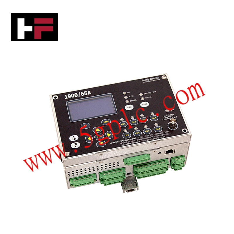
The Bently Nevada 1900/27-01, also cataloged as the 1900/27 Vibration Monitor, operates as a dedicated hardware component for single-channel vibration signal conditioning and machinery protection within 1900 Series monitoring platforms.
Hardware Specifications
| Parameter | Specification |
|---|---|
| Model | 1900/27-01 |
| Brand | Bently Nevada |
| Origin | USA |
| Weight | 0.64 kg (1.40 lbs) |
| Dimensions | Standard 1900 Series monitor footprint |
| Operating Temp | -30 deg C to +65 deg C (-22 deg F to +149 deg F) |
| Power Consumption | 60 mA maximum current draw |
| Input Voltage | 110 VAC, 50/60 Hz |
| Channel Configuration | Single-channel dynamic vibration input |
| Alarm Functions | Adjustable time delay trip logic |
Dynamic Vibration Processing and Gap Voltage Validation
The 1900/27-01 conditions continuous dynamic signals originating from proximity probe transducers or velocity sensors. Internal processing circuits apply precise eddy-current probe scaling to compute true peak-to-peak shaft vibration amplitudes or overall casing vibration levels. During commissioning and system health monitoring, DC gap voltage validation verifies proper transducer mechanical bias voltage, ensuring target proximity sensors remain centered within their linear dynamic range. Configurable time delay alarms prevent false machinery trips resulting from transient operational shocks during startup or load changes.
Frequently Asked Questions
Q: How does the adjustable time delay feature function on the 1900/27-01 monitor relay logic?
A: The onboard time delay circuit delays relay contact activation for a preset duration following a threshold breach to prevent spurious trips caused by short-duration dynamic spikes.
Q: What power input supply parameters are required to operate the 1900/27-01 module?
A: The module requires an AC line supply of 110 VAC at 50/60 Hz, drawing a maximum operating current of 60 mA.
Field Installation Guidelines
- Ensure main power is disconnected from the 1900 Series panel before installing or wiring the monitor unit.
- Mount the 1900/27-01 securely into its designated chassis slot or panel cutout using original mounting hardware.
- Connect incoming 110 VAC power conductors to the assigned AC power input terminals.
- Terminate transducer signal and common leads at the channel input terminals, using shielded twisted-pair cabling.
- Ground signal cable drain wires at a single termination point on the system chassis ground bar to suppress ground loop noise pickup.
Additional Information
- 100% Genuine Parts: All products are original and authentic, ensuring reliable industrial performance.
- 30-Day Refund Guarantee: Return any in-stock item within 30 days in original, unopened packaging for a full refund (excluding shipping and fees).
- 12-Month Warranty: Covers defects in materials or workmanship; excludes misuse, normal wear, or unauthorized modifications.
- Worldwide Shipping: We ship via USPS, UPS, FedEx, and DHL. Delivery times vary by country and may be subject to customs or import fees.
- Support & Contact: Technical and warranty assistance is available anytime. Contact us here: Contact.
- Purchase Guidance: Check product specifications and compatibility carefully before ordering to ensure proper application.




Tech & Buying Guide

Why 24V DC Power Supplies Standardize Modern Industrial Automation
Industrial control cabinets worldwide rely on 24V DC as the universal power standard for field instrumentation, sensors, and controllers. Walk into any manufacturing plant, and you will find PLCs, human-machine interfaces (HMIs), and smart actuators running on extra-low voltage DC. Standardizing on 24V DC enhances operational safety, lowers cabinet footprint, and maintains steady control performance across factory networks.

Essential Motion Control Commands: A Practical Guide for Engineers
Automation engineers often rely on precise position and speed control to drive modern factory machinery. Modern industrial systems, such as Programmable Logic Controllers (PLCs) and Distributed Control Systems (DCS), depend heavily on standardized motion instructions. Mastering these commands ensures operational safety, protects mechanical components, and optimizes cycle times across production lines.
Mastering Modern Industrial Joystick Controls in Heavy Automation
Industrial joysticks play a pivotal role in human-machine interaction across heavy material handling and mobile hydraulics. These tactile controllers translate complex operator movements into precise electrical signals for PLCs, motion controllers, and DCS networks. Consequently, selecting and installing the right joystick architecture ensures operator safety, reduces fatigue, and optimizes equipment performance.