










Product Details
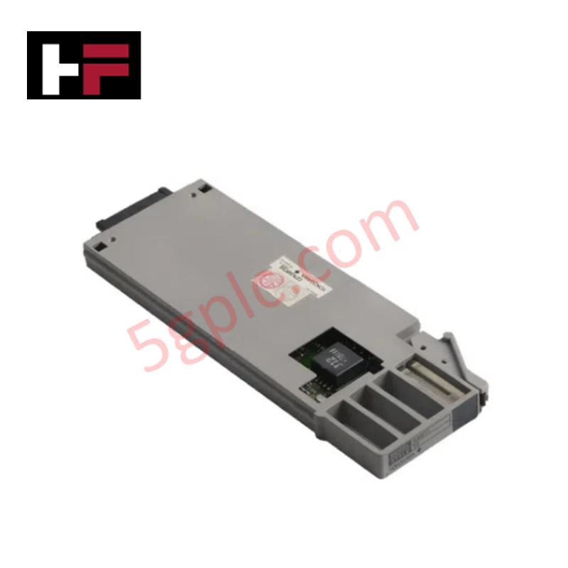
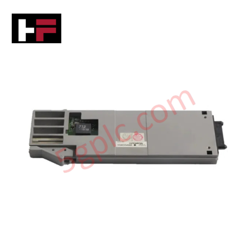
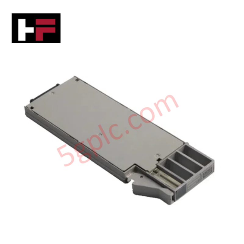
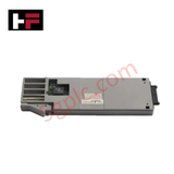
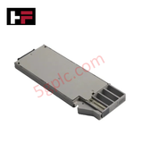
The YOKOGAWA AAM21 S2, also cataloged as the AAM21 Analog Input Module, operates as a dedicated hardware component for dual-channel isolated analog voltage and current signal acquisition within YOKOGAWA CENTUM control systems.
Suffix Breakdown & Model Matrix
The catalog designation for the AAM21-S2 defines the base hardware architecture and revision parameters:
- Base Model (AAM21): Analog Input Module architecture for voltage and current signal acquisition
- Suffix ( S2): Hardware revision 2 designating standard nest mounting and interface parameter set
Hardware Specifications
| Parameter | Specification |
|---|---|
| Model | AAM21 S2 |
| Brand | YOKOGAWA |
| Origin | Japan |
| Operating Temp | -10 to 55 deg C |
| Power Consumption | 24 VDC (+/-10%) |
| Input Channels | 2 channels (isolated) |
| Input Ranges | 0 to 10 V, +/-10 V, 4 to 20 mA, 0 to 20 mA |
| Measurement Accuracy | +/-0.1% of full scale |
| Resolution | 16-bit |
| Sampling Rate | 10 ms/ch (typical) |
| Isolation Voltage | 1500 VAC channel-to-channel |
Channel-to-Channel Isolation and 4-20 mA HART Loop Signal Acquisition
The AAM21-S2 provides 1500 VAC galvanic isolation between individual channels and internal backplane logic to prevent ground loop currents and suppress common-mode electrical noise. Operating at a 16-bit analog-to-digital conversion resolution with a 10 ms per channel sampling cycle, the module converts standard process signals—including 4-20 mA HART loop protocol field devices and +/-10 V transducers—into digital data frames for DCS backplane transmission.
Frequently Asked Questions
Q: What input signal ranges can be configured on the AAM21-S2 module?
A: The module accepts 0 to 10 V DC and +/-10 V DC voltage inputs, as well as 0 to 20 mA DC and 4 to 20 mA DC current inputs across its 2 isolated channels.
Q: What is the dielectric isolation rating between the individual input channels?
A: The module features channel-to-channel galvanic isolation rated at 1500 VAC to prevent cross-talk and signal distortion in noise-prone industrial environments.
Field Installation Guidelines
De-energize rack power prior to mounting or removing the AAM21-S2 module in the system I/O node slot. Observe electrostatic discharge (ESD) protection procedures, wearing a grounded wrist strap when handling the card. Align the module with guide rails and seat the rear connector firmly into the backplane socket, securing top and bottom retaining screws to establish frame ground continuity. Wire analog inputs using shielded twisted-pair cables, bonding the shield wire to earth ground at a single cabinet termination point to prevent ground loops. Maintain physical separation between low-voltage signal cables and AC power conductors.
Additional Information
- 100% Genuine Parts: All products are original and authentic, ensuring reliable industrial performance.
- 30-Day Refund Guarantee: Return any in-stock item within 30 days in original, unopened packaging for a full refund (excluding shipping and fees).
- 12-Month Warranty: Covers defects in materials or workmanship; excludes misuse, normal wear, or unauthorized modifications.
- Worldwide Shipping: We ship via USPS, UPS, FedEx, and DHL. Delivery times vary by country and may be subject to customs or import fees.
- Support & Contact: Technical and warranty assistance is available anytime. Contact us here: Contact.
- Purchase Guidance: Check product specifications and compatibility carefully before ordering to ensure proper application.




Tech & Buying Guide

Demystifying Open Platform Communication (OPC): The Backbone of Industrial Interoperability
Interoperability remains a cornerstone requirement for modern smart factories and process automation. Open Platform Communication (OPC) bridges the gap between disparate hardware platforms, control systems, and visualization software. By establishing a universal communication standard, OPC allows field controllers, SCADA platforms, and enterprise software from different vendors to exchange real-time data seamlessly.

Understanding Siemens PLC Memory Cards: MMC, SMC, and SD Solutions in Industrial Automation
Memory management plays a pivotal role in maintaining control system reliability across modern manufacturing plants. Industrial control systems rely on specialized memory cards to store project logic, firmware updates, and retentive system data. Siemens uses several memory architectures, including Micro Memory Cards (MMC) and SIMATIC Memory Cards (SMC). Engineers must understand these hardware variations to ensure zero data loss and minimize downtime during maintenance routines.

Redefining Control Systems: The Rise of Flexible I/O Modules in Industrial Automation
Conventional input-output architectures often limit engineering agility and inflate long-term inventory costs. Today, Flexible Input/Output Modules (FIOM) are transforming how control system engineers design, commission, and maintain automation infrastructure. By allowing individual channel software configuration, FIOM technology bridges the gap between rigid hardware design and dynamic plant requirements.