










Product Details
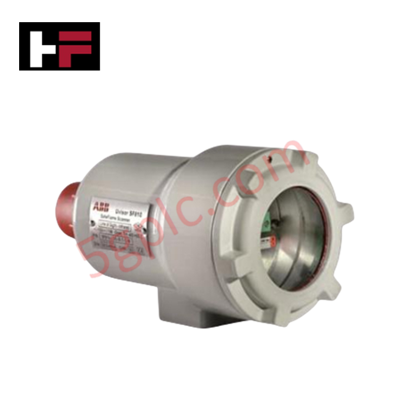
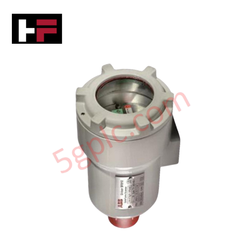
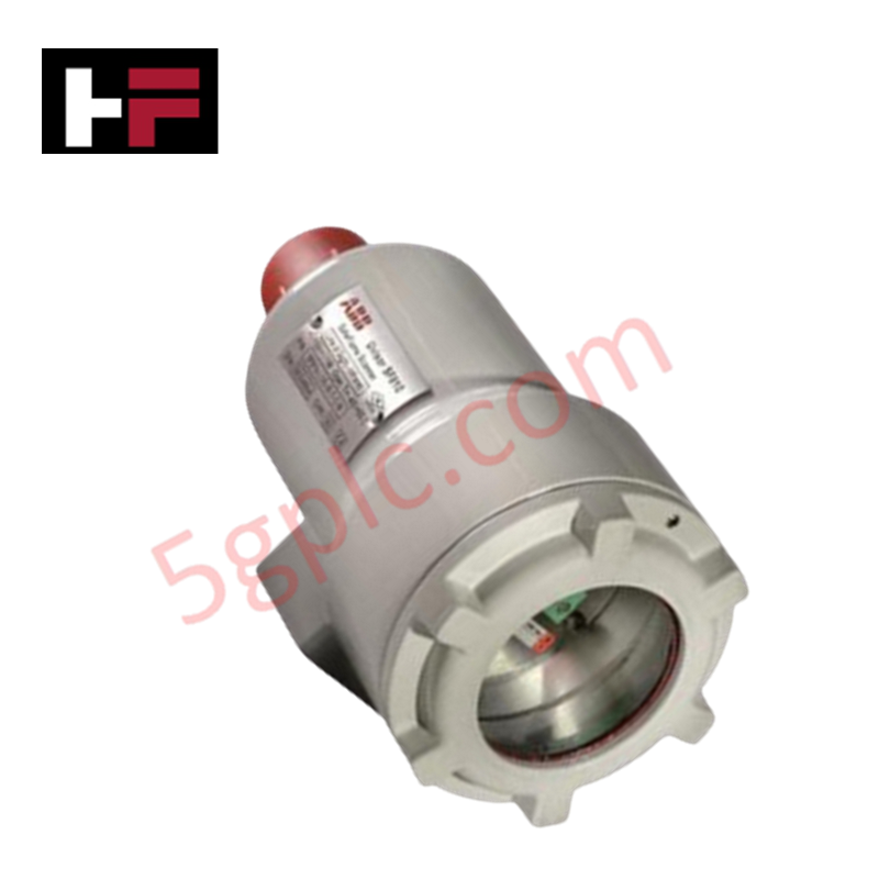
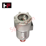
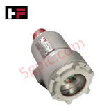
The ABB SF810-LOS-IR-TL-CW, also cataloged as the SF810-LOS-IR-CW Signal Processor Unit, operates as a dedicated hardware component for infrared flame scanning and optical spectral monitoring within industrial combustion management systems. The physical module acts as a line-of-sight (L.O.S.) infrared scanner head, detecting flame flicker frequencies and converting optical radiation parameters into electronic data packets. Equipped with a 3/4 inch threaded mounting assembly, this sensor unit interfaces with local control circuits to provide discrete combustion profiling without signal distortion.
Hardware Specifications
| Parameter | Specification |
|---|---|
| Model | SF810-LOS-IR-TL-CW |
| Brand | ABB |
| Origin | Sweden / China |
| Weight | 0.1 kg |
| Dimensions | 2 cm x 10.5 cm x 11 cm |
| Operating Temp | 0 to +60 deg C (Standard industrial parameters apply) |
| Power Consumption | Circuit loop dependent |
| Detection Mechanism | Line-of-Sight (L.O.S.) Infrared (IR) Sensor |
| Mechanical Interface | 3/4 inch threaded throat |
Firmware Flash Compatibility
The SF810-LOS-IR-TL-CW processor unit is calibrated to align with central logic processing architectures via integrated firmware flash compatibility standards. Optical parameters compiled by the infrared sensor array are indexed against internal frequency baselines, validating flame presence within fixed millisecond scanning windows. This synchronization prevents timing drift across system networks, allowing local processing subroutines to execute safety interlocks or parameter logging without data corruption during prolonged burner operation.
Frequently Asked Questions
Q: How does the SF810-LOS-IR-TL-CW handle hot-swapping or field removal while the combustion control loop is active?
A: Uncoupling or unseating this scanner head while the underlying signal conditioning loop is active will break the continuous input impedance line. This triggers an immediate false flame failure trip sequence across adjacent burner management systems and risks transient voltage induction on the signal carrier.
Q: What is the mechanical function of the 3/4 inch thread integrated into this scanner housing?
A: The 3/4 inch thread serves as the rigid pressure-sealed mechanical junction point. It locks the L.O.S. IR sensor tube into the burner sight pipe assembly, maintaining optical alignment and preventing high-pressure flue gas bypass.
Q: Does the unit utilize internal cooling configurations to prevent infrared sensor drift?
A: This model relies on passive thermal dissipation through its specialized housing. In high-temperature ambient environments, a continuous stream of dry instrument air must be supplied through the sight tube to keep the lens clear of debris and maintain internal operating temperatures within specified parameters.
Field Installation Guidelines
The SF810-LOS-IR-TL-CW scanner head must be threaded square into the 3/4 inch sight pipe union until fully engaged. Ensure that the line-of-sight alignment provides an unobstructed view into the primary combustion zone of the flame. All connection cables must be shielded to prevent common-mode noise, with the bare copper drain wire grounded exclusively at the control cabinet ground terminal block. Route the sensor lines away from high-voltage igniter transformers or three-phase power lines to eliminate magnetic interference.
Additional Information
- 100% Genuine Parts: All products are original and authentic, ensuring reliable industrial performance.
- 30-Day Refund Guarantee: Return any in-stock item within 30 days in original, unopened packaging for a full refund (excluding shipping and fees).
- 12-Month Warranty: Covers defects in materials or workmanship; excludes misuse, normal wear, or unauthorized modifications.
- Worldwide Shipping: We ship via USPS, UPS, FedEx, and DHL. Delivery times vary by country and may be subject to customs or import fees.
- Support & Contact: Technical and warranty assistance is available anytime. Contact us here: Contact.
- Purchase Guidance: Check product specifications and compatibility carefully before ordering to ensure proper application.









Tech & Buying Guide

Demystifying CPU Communication Ports in Siemens PLC Architectures
Industrial automation relies heavily on robust data exchange between devices. Without seamless connectivity, field instruments, network switches, human-machine interfaces, and programmable logic controllers cannot coordinate effectively. Therefore, understanding the various CPU communication ports available in Siemens hardware ensures efficient factory automation design and seamless system integration.

Mastering the Siemens PLC Scan Cycle: How the CPU Executes Automation Programs
Industrial automation relies heavily on programmable logic controllers (PLCs) to manage complex manufacturing processes. Many engineers dive straight into programming without mastering the underlying architecture. However, understanding how a PLC CPU executes a program ensures reliable system design. Therefore, mastering the scan cycle optimizes both performance and troubleshooting in modern control systems.

How to Connect to Siemens S7 PLCs: 5 Essential Communication Methods
Establishing a reliable hardware link between a programming terminal and a Siemens SIMATIC controller is essential for engineering workflows. Field engineers rely on distinct physical layers, ranging from legacy serial connections to high-speed Industrial Ethernet protocols. Modern factory automation environments prioritize fast data transfer and seamless driver integration. Selecting the correct connection method simplifies program downloads, online monitoring, and system troubleshooting in complex control systems.