










Product Details
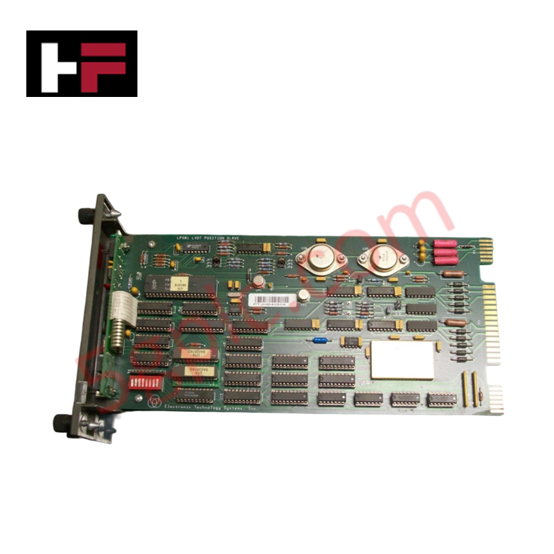
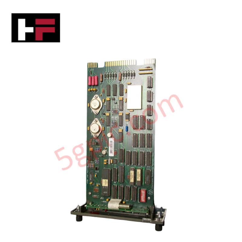
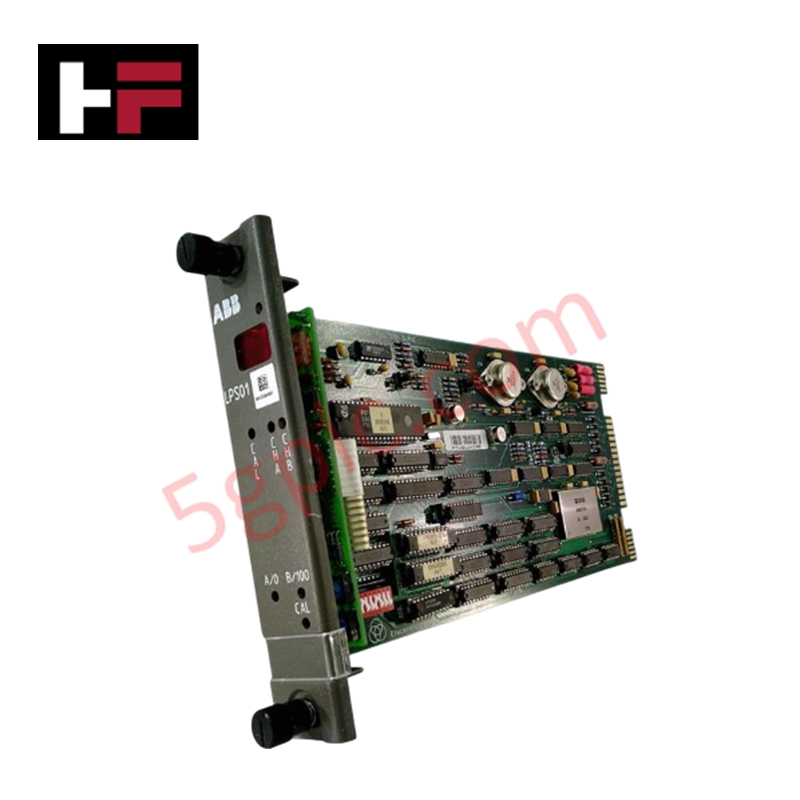
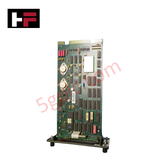
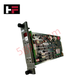
The ABB LPS01, also cataloged as the LPS01 LVDT Position Module, operates as a dedicated hardware component for Linear Variable Differential Transformer (LVDT) sensor signal processing within ABB Bailey Infi 90 system platforms.
Hardware Specifications
| Parameter | Specification |
|---|---|
| Model | LPS01 |
| Brand | ABB (Bailey) |
| Origin | United States |
| Weight | 0.4 kg (0 lbs 12.9 oz) |
| Dimensions | 33.0 cm x 5.1 cm x 17.8 cm (13.0" x 2.0" x 7.0") |
| Operating Temp | 0 to +60 deg C (Standard industrial rack parameters) |
| Power Consumption | Sourced via Infi 90 backplane bus lines |
| Module Type | LVDT Position Module |
| System Interface | ETSI Bailey Infi 90 / Net 90 compatibility |
| Tariff Code | 8538907080 |
Profinet / EtherNet/IP Deterministic Networks and I/O Density Scaling
The positioning hardware converts raw AC voltage differentials from external inductive displacement sensors into digital register variables. This translation maintains native backplane bus communication velocity across the rack sub-assembly, shielding processor loops from analog phase shifts. The specialized signal converter allows precise I/O density scaling options within hydraulic valve actuator tracking circuits while preserving timing synchronization and balancing firmware flash compatibility markers across linked communication networks.
Frequently Asked Questions
Q: How is the LVDT excitation voltage generated and checked within the LPS01 module?
A: The excitation frequency and reference voltage are derived from integrated circuitry built directly on the board. The system monitors feedback phase alignment across the backplane connection interface to detect any secondary coil insulation degradation or short circuits.
Q: Can this positioning module be removed under live system rack power?
A: Module handling constraints are dictated by the specific hosting frame. To prevent loop tracking faults or unintended shutdown variables in the master controller registers, the associated servo loops must be swapped to manual operation or safely bypassed prior to module removal.
Field Installation Guidelines
- Chassis Card Cage Insertion: Align the PCB edges within the designated slot tracks of the Infi 90 rack enclosure. Gently press the unit inward until the rear pins seat completely into the backplane mating connector.
- Transducer Cable Shielding: Terminate LVDT extension lines using dedicated shielded twisted pairs. Ground the outer copper braiding exclusively at the cabinet bulkhead earth bar to block magnetic noise interference from local power cables.
- Field Cable Routing: Separate sensitive AC sensor signal wiring from high-power motor lines and inductive valve solenoid paths to maintain signal resolution.
Additional Information
- 100% Genuine Parts: All products are original and authentic, ensuring reliable industrial performance.
- 30-Day Refund Guarantee: Return any in-stock item within 30 days in original, unopened packaging for a full refund (excluding shipping and fees).
- 12-Month Warranty: Covers defects in materials or workmanship; excludes misuse, normal wear, or unauthorized modifications.
- Worldwide Shipping: We ship via USPS, UPS, FedEx, and DHL. Delivery times vary by country and may be subject to customs or import fees.
- Support & Contact: Technical and warranty assistance is available anytime. Contact us here: Contact.
- Purchase Guidance: Check product specifications and compatibility carefully before ordering to ensure proper application.









Tech & Buying Guide

Demystifying the DDE Protocol in Legacy Industrial Automation Systems
Modern control systems rely heavily on seamless interprocess communication to exchange operational data between software programs. Microsoft first introduced the Dynamic Data Exchange (DDE) protocol in 1987 to enable real-time data sharing. In factory automation, DDE served as an early bridge between control software and Windows desktop applications. Therefore, understanding DDE mechanics provides crucial insights into how legacy industrial networks established software-level connectivity.

Demystifying CPU Communication Ports in Siemens PLC Architectures
Industrial automation relies heavily on robust data exchange between devices. Without seamless connectivity, field instruments, network switches, human-machine interfaces, and programmable logic controllers cannot coordinate effectively. Therefore, understanding the various CPU communication ports available in Siemens hardware ensures efficient factory automation design and seamless system integration.

Mastering the Siemens PLC Scan Cycle: How the CPU Executes Automation Programs
Industrial automation relies heavily on programmable logic controllers (PLCs) to manage complex manufacturing processes. Many engineers dive straight into programming without mastering the underlying architecture. However, understanding how a PLC CPU executes a program ensures reliable system design. Therefore, mastering the scan cycle optimizes both performance and troubleshooting in modern control systems.