










Product Details
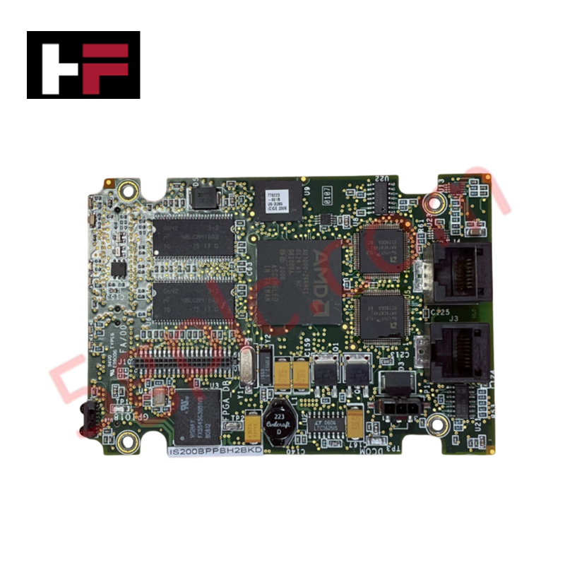
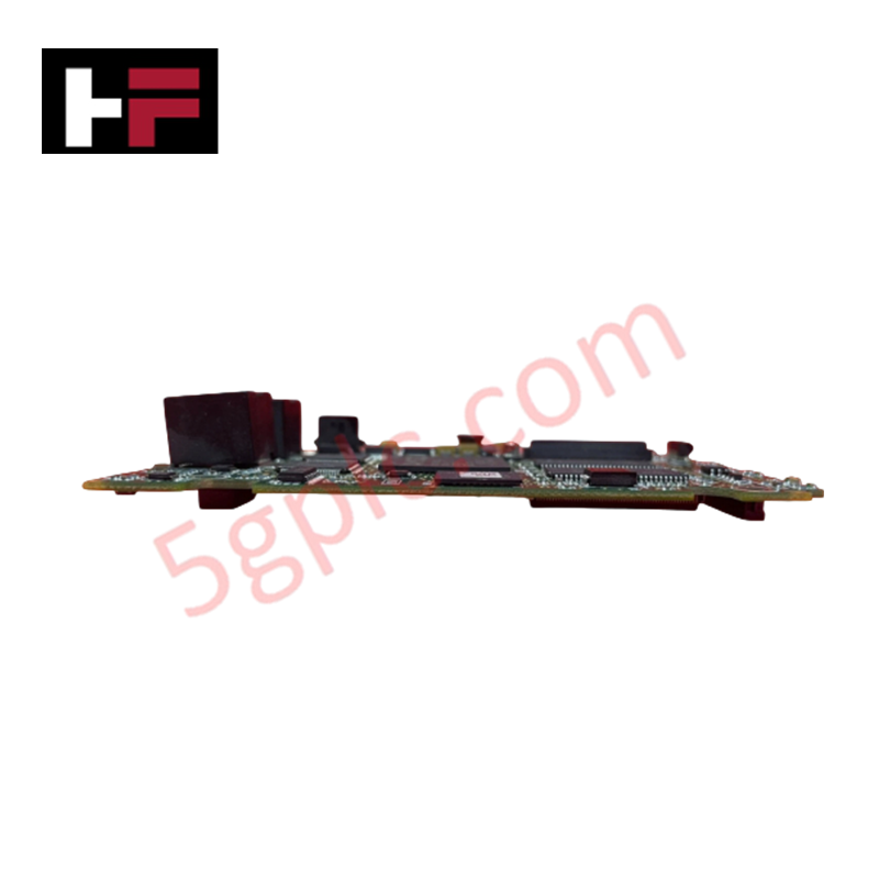
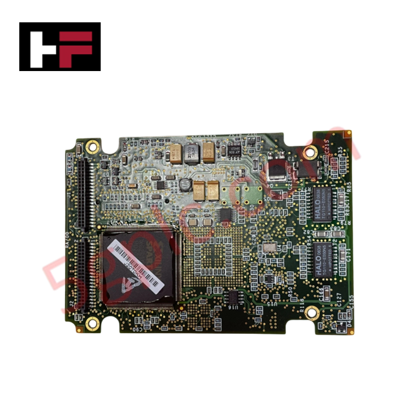
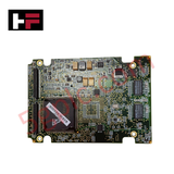
The General Electric IS200BPPBH2B, also cataloged as the IS200BPPBH2B Printed Circuit Board, operates as a dedicated hardware component for signal routing and auxiliary circuit support within Mark VI turbine control system platforms.
Hardware Specifications
| Parameter | Specification |
|---|---|
| Model | IS200BPPBH2B |
| Brand | General Electric |
| Dimensions | Compact (add-on board format) |
| Mounting | 4-point screw standoff (motherboard mount) |
| Component Features | AMD memory chip, inductor coil, dual status LEDs |
Profinet and Deterministic Network Operations
The IS200BPPBH2B functions as an add-on expansion module requiring integration with a host motherboard via factory-drilled, brass-plated mounting holes. The board facilitates circuit-level support through onboard integrated circuits and transistors, maintaining data path integrity within the Mark VI control architecture. Deterministic communication is supported via the board's vertical connectors and phone jack interfaces, which align with host-board communication bus requirements. Firmware flash compatibility and bus velocity are dictated by the host circuit board's specific revision and the overarching Mark VI control cabinet configuration.
Frequently Asked Questions (FAQ)
Q: How is the IS200BPPBH2B secured to the motherboard?
A: The board utilizes four corner-mounted standoffs and screws, which interface with factory-drilled holes on the motherboard to ensure mechanical stability and ground continuity.
Q: What is the purpose of the dual LEDs on the board edge?
A: The onboard LEDs provide visual status indicators for circuit health and signal connectivity, assisting in real-time diagnostic monitoring within the host control assembly.
Field Installation Guidelines
- Mechanical Mounting: Align the board's mounting holes with the standoff points on the motherboard. Ensure that the curved edges of the PCB are oriented to provide necessary clearance for existing motherboard-mounted components.
- Connector Engagement: Carefully seat the vertical connectors into the corresponding motherboard headers. Apply even pressure across the PCB to ensure that all pins are fully engaged without bending.
- Electrical Safety: Ensure the host system is de-energized before mounting or removing the board to prevent short-circuiting the integrated circuits or damaging the sensitive memory components.
- ESD Precautions: Use a grounded wrist strap and an anti-static workstation during installation, as the surface-mount components and integrated memory chips are susceptible to electrostatic discharge.
Additional Information
- 100% Genuine Parts: All products are original and authentic, ensuring reliable industrial performance.
- 30-Day Refund Guarantee: Return any in-stock item within 30 days in original, unopened packaging for a full refund (excluding shipping and fees).
- 12-Month Warranty: Covers defects in materials or workmanship; excludes misuse, normal wear, or unauthorized modifications.
- Worldwide Shipping: We ship via USPS, UPS, FedEx, and DHL. Delivery times vary by country and may be subject to customs or import fees.
- Support & Contact: Technical and warranty assistance is available anytime. Contact us here: Contact.
- Purchase Guidance: Check product specifications and compatibility carefully before ordering to ensure proper application.


Tech & Buying Guide
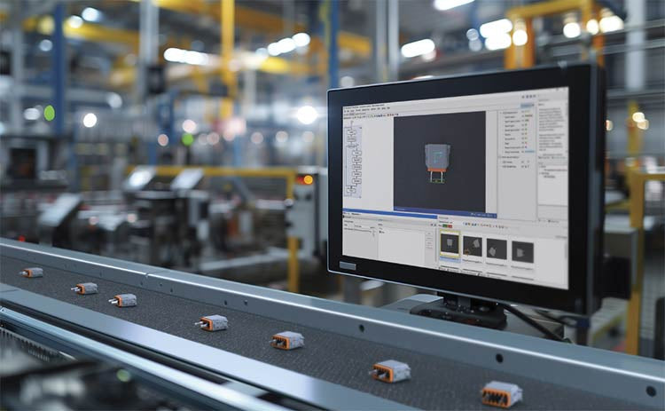
Modern Industrial Automation: Transforming Safety and Efficiency in Mining Operations
Industrial automation has evolved from a simple manufacturing tool into the operational backbone of high-risk sectors. Modern mining operations increasingly rely on advanced control systems, programmable logic controllers (PLCs), distributed control systems (DCS), and artificial intelligence to address deep-underground hazards. By replacing manual labor in high-risk zones, factory automation technologies protect personnel while significantly boosting operational throughput.

Step-by-Step System Cabinet Health Check Guide for PLC and DCS Infrastructure
