










Product Details
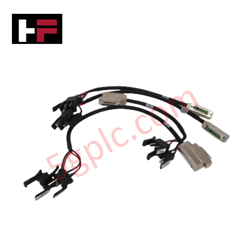
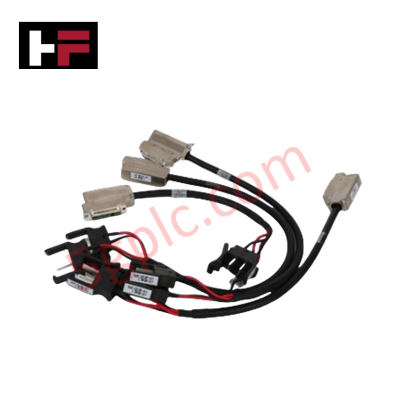
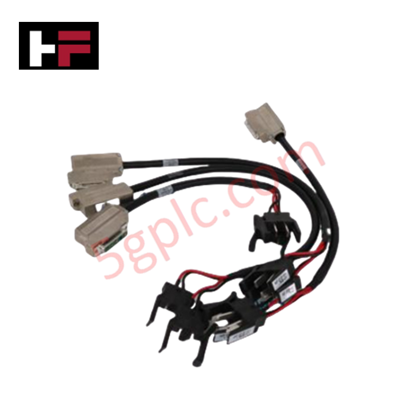
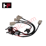
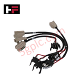
Configured for high-speed deterministic signal transmission in industrial automation systems, the Honeywell GN-KRR011 51204147-001 (GN-KRR011 Fiber Optic Cable) provides direct physical/electrical execution. The hardware component establishes an optical interface link between station bus participants, zone controllers, or network components, allowing uncorrupted voice, data, and I/O tracking signals to route seamlessly into the C300 controller topology.
Hardware Specifications
| Parameter | Specification |
|---|---|
| Model | GN-KRR011 51204147-001 |
| Brand | Honeywell |
| Series / Module Type | Series 8 / C300 Redundancy Network Component |
| Origin | USA |
| Weight | 0.2 kg |
| Dimensions | 2 meters (Total assembly length) |
| Operating Temp | -40 to +70 deg C |
| Power Supply | 24 VDC system standard reference voltage |
| Cable Type | Simplex, multimode HCS fiber optic |
| Connectors | LC connector (End A), ST connector (End B) |
| Jacket Material | PVC insulation and jacket |
| Data Capabilities | Synchronous voice, data, and IO Link data streams |
| System Compatibility | Honeywell C300 Controllers, IO Link, ISA100 network modules |
4-20 mA HART Loop Protocol and Channel-to-Channel Isolation
The GN-KRR011 51204147-001 multimode HCS fiber optic assembly delivers total electrical channel-to-channel isolation between synchronized C300 controllers or remote IO Link interfaces. By replacing copper wire with an optical link, it completely suppresses cross-talk, common-mode voltage spikes, and ground loops that degrade analog input loops. This configuration supports high-frequency digital traffic alongside traditional 4-20 mA HART loop protocol parameters, ensuring that distributed field instruments communicate accurate process values to the centralized DCS architecture without signal loss.
Frequently Asked Questions
Q: How does this optical cable maintain structural protection against ground differentials between controllers located in separate electrical rooms?
A: Because the multimode fiber architecture relies entirely on light wave propagation, there is no metallic contact. This provides absolute channel-to-channel isolation, completely neutralizing voltage offsets and preventing dangerous fault currents from running along the system bus.
Q: Can the cable bend radius be altered during high-density tray routing?
A: The cable uses a durable HCS fiber base with a PVC jacket, but the minimum dynamic bend radius specified by the manufacturer must be maintained. Tight bends will cause macro-bending loss, which attenuates the light signal and degrades data frame integrity across the IO Link.
Field Installation Guidelines
- Routing and Physical Path Separation: Lay the fiber optic assembly inside dedicated low-voltage wire ways. Keep it away from high-voltage AC cables to prevent mechanical crushing or tearing from heavy physical lines.
- Connector Connection Sequence: Remove the protective dust caps immediately before mating the interfaces. Insert the LC connector end into the C300 IOTA or network transceiver port until it clicks securely, then turn and lock the ST connector end onto its matching node.
- Pulling Force Limits: Never apply axial pulling force directly to the LC or ST connector boots during installation. Pull gently on the external PVC cable jacket to prevent cracking the inner glass-core junction.
- Thermal Monitoring: Ensure the cable run stays within the specified -40 to +70 deg C thermal limit. Do not place the cable against steam pipes, high-output heat sinks, or unventilated surfaces inside the cabinet.
Additional Information
- 100% Genuine Parts: All products are original and authentic, ensuring reliable industrial performance.
- 30-Day Refund Guarantee: Return any in-stock item within 30 days in original, unopened packaging for a full refund (excluding shipping and fees).
- 12-Month Warranty: Covers defects in materials or workmanship; excludes misuse, normal wear, or unauthorized modifications.
- Worldwide Shipping: We ship via USPS, UPS, FedEx, and DHL. Delivery times vary by country and may be subject to customs or import fees.
- Support & Contact: Technical and warranty assistance is available anytime. Contact us here: Contact.
- Purchase Guidance: Check product specifications and compatibility carefully before ordering to ensure proper application.


Tech & Buying Guide

Demystifying the DDE Protocol in Legacy Industrial Automation Systems
Modern control systems rely heavily on seamless interprocess communication to exchange operational data between software programs. Microsoft first introduced the Dynamic Data Exchange (DDE) protocol in 1987 to enable real-time data sharing. In factory automation, DDE served as an early bridge between control software and Windows desktop applications. Therefore, understanding DDE mechanics provides crucial insights into how legacy industrial networks established software-level connectivity.

Demystifying CPU Communication Ports in Siemens PLC Architectures
Industrial automation relies heavily on robust data exchange between devices. Without seamless connectivity, field instruments, network switches, human-machine interfaces, and programmable logic controllers cannot coordinate effectively. Therefore, understanding the various CPU communication ports available in Siemens hardware ensures efficient factory automation design and seamless system integration.

Mastering the Siemens PLC Scan Cycle: How the CPU Executes Automation Programs
Industrial automation relies heavily on programmable logic controllers (PLCs) to manage complex manufacturing processes. Many engineers dive straight into programming without mastering the underlying architecture. However, understanding how a PLC CPU executes a program ensures reliable system design. Therefore, mastering the scan cycle optimizes both performance and troubleshooting in modern control systems.