


Product Details
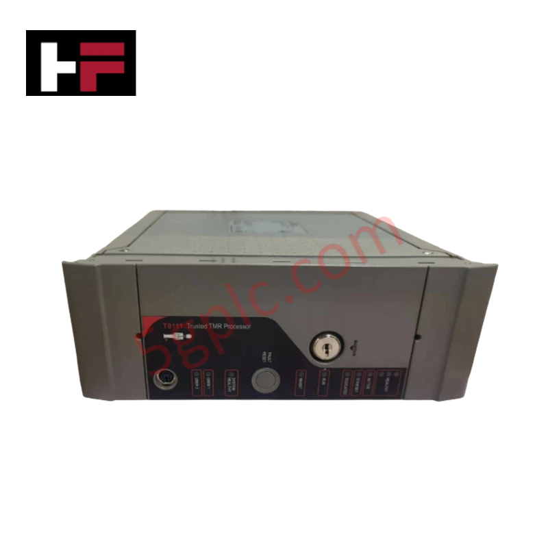
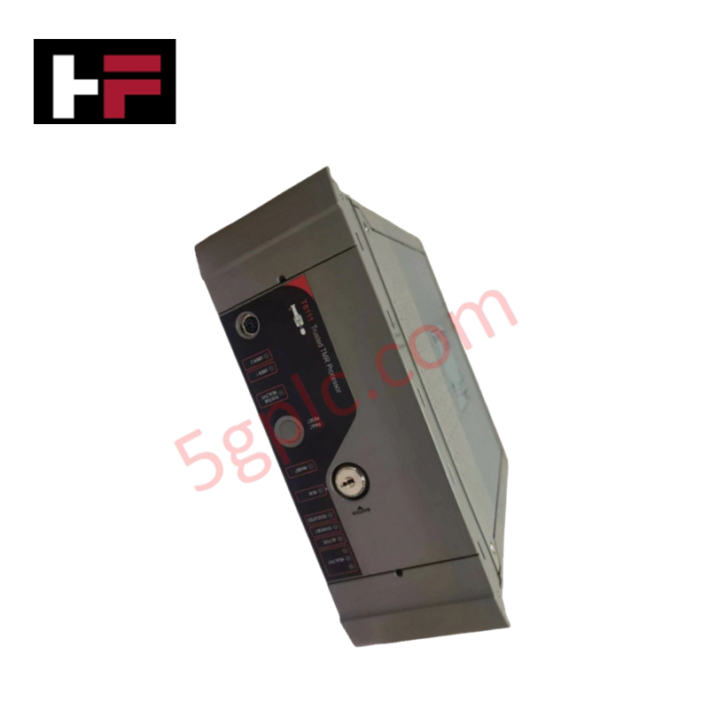
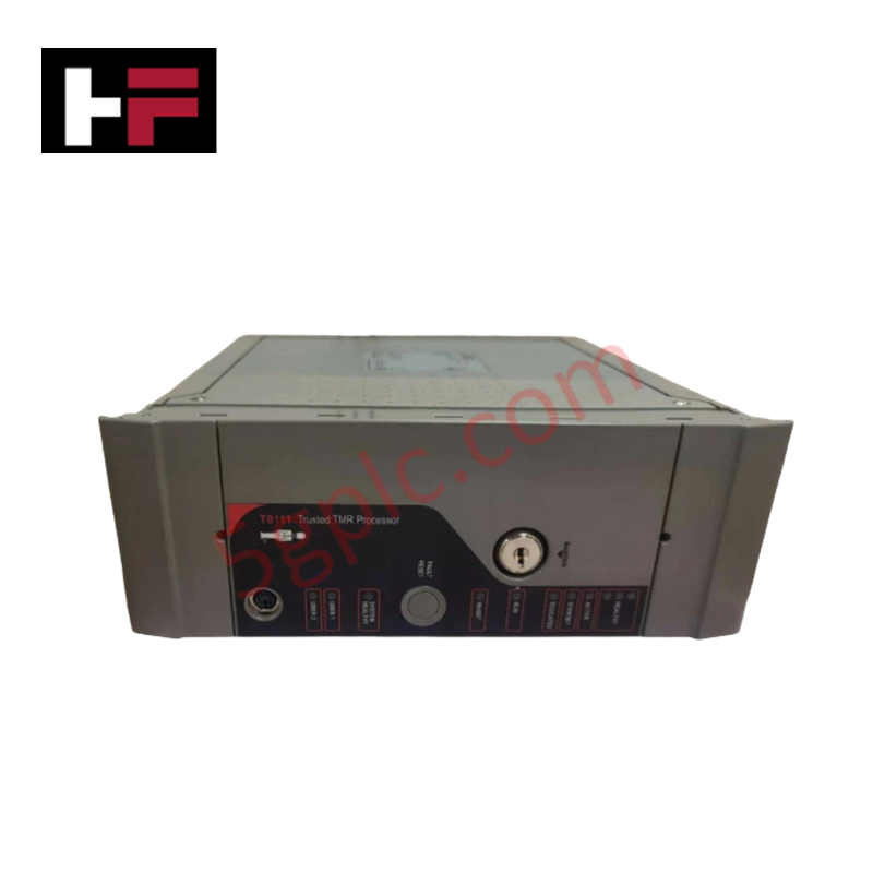
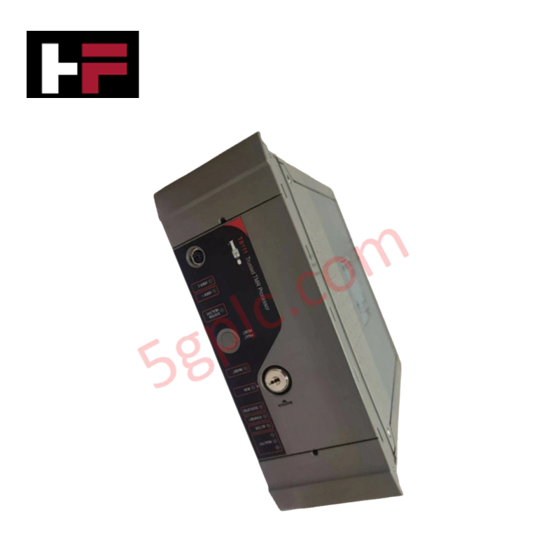
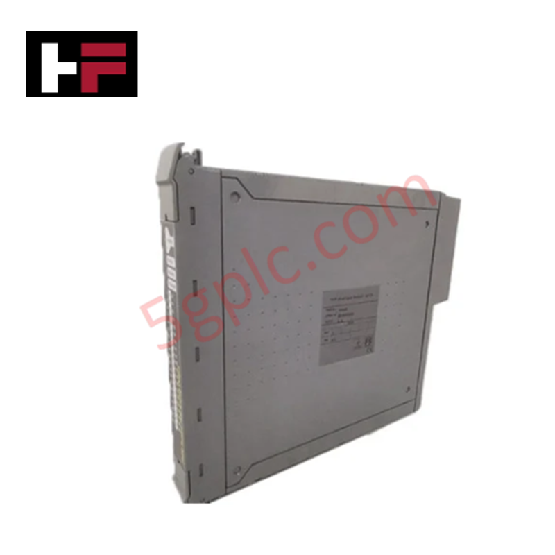
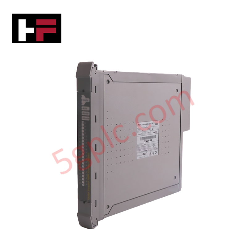
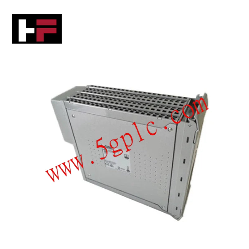
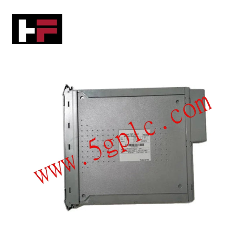
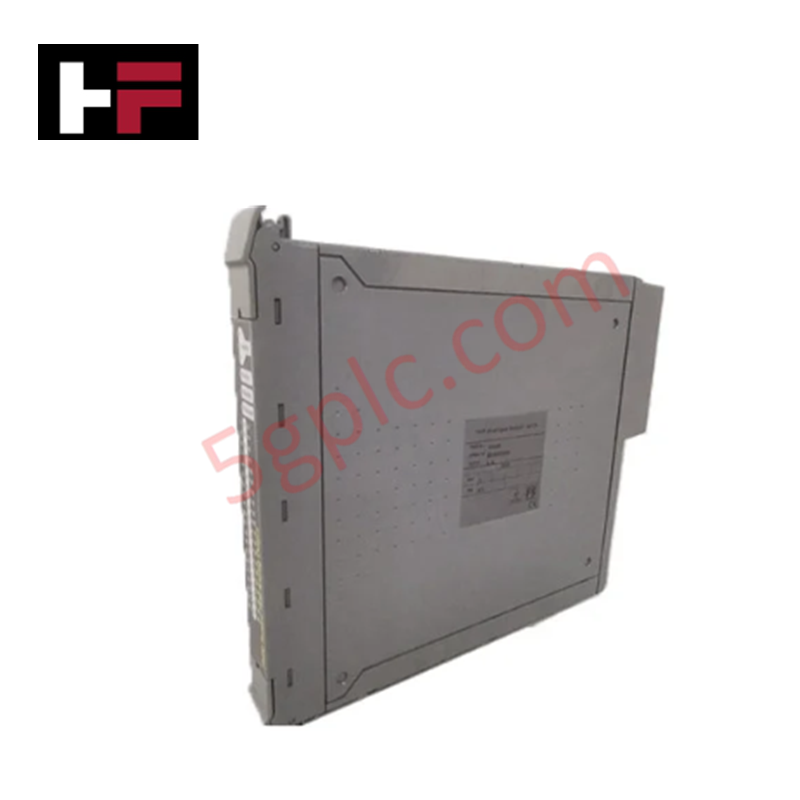
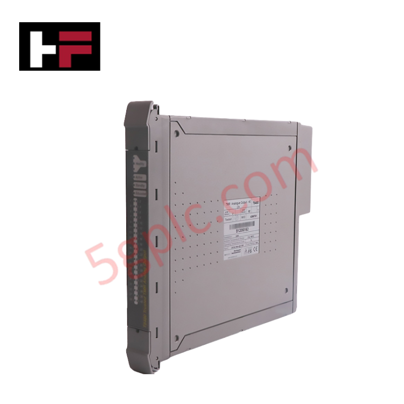
The Honeywell 2MLR-DBST, also cataloged as the 2MLR-DBST Expansion Driver, operates as a dedicated hardware component for deterministic rack expansion and CPU interface bus driving within 2MLR redundant CPU platforms. Mounted directly at the CPU connector position of an extension base, it drives electrical logic communication over twisted-pair CAT5 media across distance intervals up to 100 m between extension chassis units.
Hardware Specifications
| Parameter | Specification |
|---|---|
| Model | 2MLR-DBST |
| Brand | Honeywell |
| Origin | Industrial Standard Assembly |
| Weight | 0.1 kg (Shipping Weight: 1.5 kg) |
| Dimensions | Base Module Form Factor |
| Operating Temp | 0 to 55 deg C |
| Power Consumption | Backplane Powered |
| Compatible CPUs | 2MLR-CPUH/T, 2MLR-CPUH/F |
| Media Type | Electrical (TP / CAT5) |
| Max Inter-Base Distance | 100 m |
| Loader Interface | Extension Drive USB |
| Station Number Range | 1 to 31 |
| Mounting Position | CPU slot (CPU0 connector) on extension base |
4-20 mA HART Loop Protocol & DCS Integration
The 2MLR-DBST maintains high-integrity physical layer signals between local CPU bases and remote I/O chassis carrying field process telemetry. Built-in channel-to-channel isolation on the backplane communication drivers mitigates ground potential shifts and cross-talk noise between expansion nodes. This isolation preserves measurement accuracy for critical 4-20 mA HART loop instrumentation and DCS analog cards attached to remote extension racks across long copper cable runs.
Frequently Asked Questions
Q: What happens if an invalid station number outside the 1 to 31 range is assigned to the 2MLR-DBST?
A: Assigning a station address outside the permitted range of 1 to 31 triggers an immediate system configuration error, preventing backplane bus synchronization with the main CPU.
Q: Can the loader connection on the 2MLR-DBST be accessed while mounted on an extension base?
A: Yes, the module features a front-facing extension drive USB connector that allows programming and diagnostic loader access directly at the base site.
Field Installation Guidelines
- Power down the extension chassis completely before inserting the 2MLR-DBST into the designated CPU0 connector slot.
- Route industrial-grade TP/CAT5 cabling away from high-voltage power lines and variable frequency drives to minimize electromagnetic interference.
- Verify that the total cable distance between connected extension bases does not exceed 100 m to prevent transmission signal degradation.
- Set the station address selector to a valid integer between 1 and 31 prior to energizing the base power supply.
Additional Information
- 100% Genuine Parts: All products are original and authentic, ensuring reliable industrial performance.
- 30-Day Refund Guarantee: Return any in-stock item within 30 days in original, unopened packaging for a full refund (excluding shipping and fees).
- 12-Month Warranty: Covers defects in materials or workmanship; excludes misuse, normal wear, or unauthorized modifications.
- Worldwide Shipping: We ship via USPS, UPS, FedEx, and DHL. Delivery times vary by country and may be subject to customs or import fees.
- Support & Contact: Technical and warranty assistance is available anytime. Contact us here: Contact.
- Purchase Guidance: Check product specifications and compatibility carefully before ordering to ensure proper application.


Tech & Buying Guide

Optimizing Tank Level Control Using Proportional Algorithms in PLC Systems
Industrial automation engineers frequently encounter liquid level regulation challenges across diverse process plants. Traditional ON-OFF control mechanisms often disrupt system stability due to abrupt actuator switching. Therefore, upgrading to closed-loop architectures like proportional control yields smoother responses. In a typical PLC environment, such as Siemens TIA Portal, engineers utilize closed-loop feedback to minimize process errors without requiring full PID complexity.

Understanding Why Your PLC Enters Stop Mode: Causes and Troubleshooting
In industrial automation, programmable logic controllers (PLCs) serve as the core intelligence of modern factory automation and distributed control systems (DCS). Understanding how a PLC transitions between modes is vital for maintenance engineers. Typically, a PLC operates across four primary modes: Run, Stop, Start-Up, and Hold. When power is applied, the system immediately boots into Stop mode before initiating the Start-Up sequence. If the controller encounters a critical error during execution, it automatically reverts to Stop mode to prevent equipment damage. Therefore, monitoring these state transitions helps technicians maintain high system availability.

Comprehensive Guide to Servo Motor Drive Control Techniques in Industrial Automation
Precision motion control systems drive high-throughput manufacturing across modern industrial automation environments. Unlike standard induction motors running on basic variable frequency drives, servo motor systems deliver sub-millimeter positioning accuracy and fast dynamic response.