










Product Details
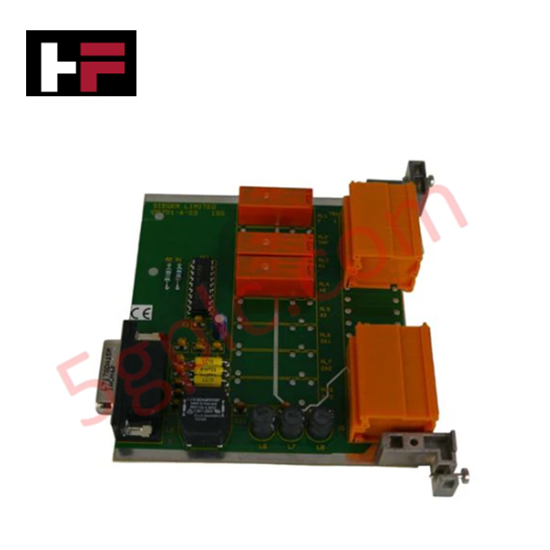
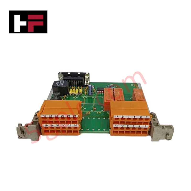
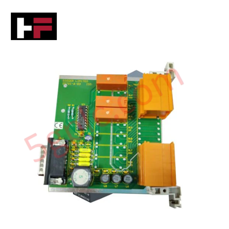
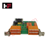
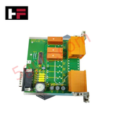
Configured for discrete signal management in System 57 gas detection platforms, the Honeywell 05701-A-0327 (05701-A-0327 Relay Card) provides direct physical execution of control logic. The module functions as a double SPCO (Single Pole Changeover) interface, facilitating the control of A1, A2, and fault relay states within the gas monitoring architecture.
Hardware Specifications
| Parameter | Specification |
|---|---|
| Model | 05701-A-0327 |
| Brand | Honeywell |
| Origin | Not specified |
| Weight | 1.2 kg |
| Dimensions | Standard System 57 card format |
| Operating Temp | Consult System 57 technical manual |
| Power Consumption | Dependent on active relay state |
| Relay Type | Double SPCO |
Channel-to-Channel Isolation
The 05701-A-0327 relay card utilizes galvanic isolation to maintain signal separation between the relay contact outputs and the controller backplane. This electrical isolation prevents ground-referenced noise from affecting the internal system logic and ensures that high-voltage switching transients on the A1, A2, or fault output circuits do not propagate back to the System 57 processing modules. Maintaining this isolation barrier is required to protect the integrity of the gas detection control loop and to prevent common-mode voltage interference during relay state transitions.
Frequently Asked Questions
Q: Is this relay card compatible with hot-swap installation in the System 57 rack?
A: No. Do not insert or remove the card while the subrack is energized. Power must be removed to prevent damage to the backplane edge connector and the internal electronic components.
Q: How should inductive loads be connected to the SPCO outputs?
A: Inductive loads must be protected by appropriate flyback diodes or RC snubbers. Failure to suppress back-EMF during relay de-energization can lead to contact pitting or failure of the isolation barrier.
Field Installation Guidelines
- Physical Mounting: Insert the module into the designated System 57 rack slot. Verify that the card is fully seated against the backplane connector before powering the rack to ensure stable electrical contact.
- Wiring Practices: Utilize shielded cabling for all field output wiring. Terminate the shield at the cabinet ground bus to minimize the risk of electromagnetic interference (EMI) coupling with sensitive sensor signals.
- Terminal Torque: Observe standard terminal block torque requirements when connecting external control wiring. Ensure all connections are secure to prevent intermittent signal states caused by mechanical vibration.
- Cable Routing: Maintain separation between low-level sensor signal cabling and high-voltage relay output wiring. Route these circuits in separate conduits or segregated wireways to satisfy industrial noise mitigation standards.
Additional Information
- 100% Genuine Parts: All products are original and authentic, ensuring reliable industrial performance.
- 30-Day Refund Guarantee: Return any in-stock item within 30 days in original, unopened packaging for a full refund (excluding shipping and fees).
- 12-Month Warranty: Covers defects in materials or workmanship; excludes misuse, normal wear, or unauthorized modifications.
- Worldwide Shipping: We ship via USPS, UPS, FedEx, and DHL. Delivery times vary by country and may be subject to customs or import fees.
- Support & Contact: Technical and warranty assistance is available anytime. Contact us here: Contact.
- Purchase Guidance: Check product specifications and compatibility carefully before ordering to ensure proper application.




Tech & Buying Guide

Demystifying CPU Communication Ports in Siemens PLC Architectures
Industrial automation relies heavily on robust data exchange between devices. Without seamless connectivity, field instruments, network switches, human-machine interfaces, and programmable logic controllers cannot coordinate effectively. Therefore, understanding the various CPU communication ports available in Siemens hardware ensures efficient factory automation design and seamless system integration.

Mastering the Siemens PLC Scan Cycle: How the CPU Executes Automation Programs
Industrial automation relies heavily on programmable logic controllers (PLCs) to manage complex manufacturing processes. Many engineers dive straight into programming without mastering the underlying architecture. However, understanding how a PLC CPU executes a program ensures reliable system design. Therefore, mastering the scan cycle optimizes both performance and troubleshooting in modern control systems.

How to Connect to Siemens S7 PLCs: 5 Essential Communication Methods
Establishing a reliable hardware link between a programming terminal and a Siemens SIMATIC controller is essential for engineering workflows. Field engineers rely on distinct physical layers, ranging from legacy serial connections to high-speed Industrial Ethernet protocols. Modern factory automation environments prioritize fast data transfer and seamless driver integration. Selecting the correct connection method simplifies program downloads, online monitoring, and system troubleshooting in complex control systems.