










Product Details
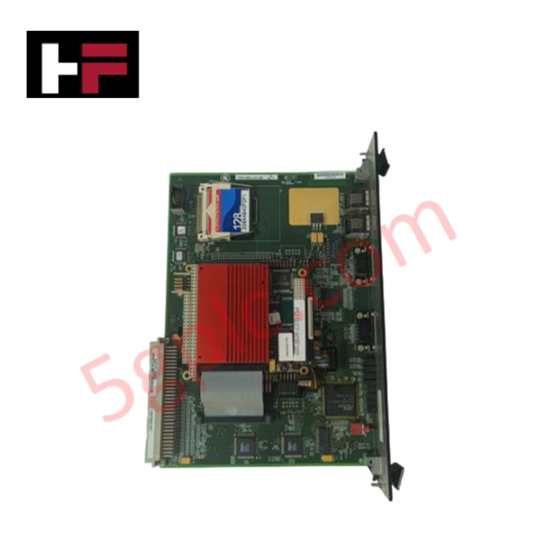
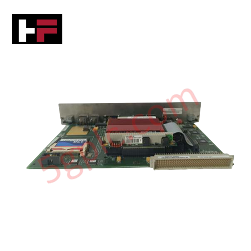
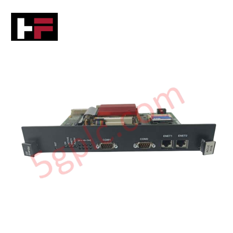
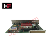
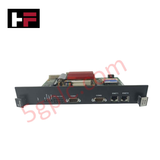
The General Electric IS215ACLEH1B, also cataloged as the IS215ACLEH1B Application Control Layer Module, operates as a dedicated hardware component for turbine control logic execution and subsystem coordination within Mark VI Speedtronic gas turbine control systems.
Hardware Specifications
| Parameter | Specification |
|---|---|
| Model | IS215ACLEH1B |
| Brand | General Electric |
| Origin | United States (USA) |
| Dimensions | 23.495 cm H x 10.795 cm W |
| Operating Temp | -30 deg C to +65 deg C |
| Input Voltage | 125 V dc |
| Output Voltage | 24 V dc |
| Mounting | DIN-rail |
| Module Type | Safety I/O Pack |
Profinet and Deterministic Network Operations
The IS215ACLEH1B utilizes high-speed internal bus communication to facilitate deterministic data exchange within the Mark VI control architecture. The module is engineered for low-latency signal processing, ensuring that turbine control logic—including speed, load, and temperature regulation—is executed within defined scan-time windows. Its integration into the backplane requires alignment with the controller firmware flash compatibility to ensure synchronized communication across the I/O pack network. The module maintains strict data integrity during high-speed polling, managing fault detection and diagnostic packet transmission without interrupting the primary control loops.
Frequently Asked Questions (FAQ)
Q: Does the IS215ACLEH1B support hot-swap functionality within the Mark VI rack?
A: Yes, the module is designed for removal and insertion while the system backplane is energized, provided the associated control loop has been safely transitioned to manual or shutdown state per site-specific safety procedures.
Q: What are the primary considerations for firmware compatibility?
A: Firmware versions must match the specific revision of the host Mark VI controller to ensure proper I/O mapping and diagnostic reporting. Consult the specific turbine control software revision documentation before field replacement.
Q: How is fault isolation managed by this module?
A: The module performs continuous self-diagnostics and monitors loop status; in the event of an internal hardware fault, it triggers a diagnostic alarm to the controller and enters a predefined safe state to prevent erroneous output signals.
Field Installation Guidelines
- Environmental Conditioning: Ensure the installation environment is free from corrosive gases and conductive dust. The module must operate within the rated temperature range of -30 deg C to +65 deg C to prevent thermal throttling or component failure.
- Mechanical Mounting: Secure the module firmly onto the designated DIN-rail. Ensure adequate clearance above and below the module to facilitate airflow for passive cooling.
- Electrical Termination: Verify that the 125 V dc input power is stable and within tolerance before engaging the module. Utilize shielded cabling for all I/O signal paths to minimize electromagnetic interference (EMI).
- Grounding: Ensure the module chassis is properly bonded to the system common ground to maintain shielding integrity and mitigate surge voltage impacts.
- Verification: Post-installation, perform a visual inspection of the status LEDs and verify the link status within the HMI interface before attempting a system-wide loop check.
Additional Information
- 100% Genuine Parts: All products are original and authentic, ensuring reliable industrial performance.
- 30-Day Refund Guarantee: Return any in-stock item within 30 days in original, unopened packaging for a full refund (excluding shipping and fees).
- 12-Month Warranty: Covers defects in materials or workmanship; excludes misuse, normal wear, or unauthorized modifications.
- Worldwide Shipping: We ship via USPS, UPS, FedEx, and DHL. Delivery times vary by country and may be subject to customs or import fees.
- Support & Contact: Technical and warranty assistance is available anytime. Contact us here: Contact.
- Purchase Guidance: Check product specifications and compatibility carefully before ordering to ensure proper application.


Tech & Buying Guide

Understanding PLC Digital Output Types: Relay, Transistor, and Triac Explained
Programmable Logic Controllers (PLCs) form the backbone of modern industrial automation systems. They interface directly with field devices such as solenoid valves, indicator lights, motor starters, and interposing relays. Selecting the correct digital output module ensures high system availability and long hardware service life.

Understanding VFD Mechanical Brake Logic and Control in Industrial Automation
Variable Frequency Drives (VFDs) play a crucial role in modern industrial automation by controlling motor speed, torque, and acceleration. However, high-inertia loads and vertical lifting systems require precise mechanical braking logic to ensure operational safety and prevent equipment damage.

Why Programmable Logic Controllers Drop into Stop Mode: An Expert Analysis
Industrial automation systems rely heavily on Programmable Logic Controllers (PLCs) to maintain uninterrupted production. When a PLC unexpectedly shifts from Run to Stop mode, whole manufacturing lines stall.
As control systems evolve across modern factory automation, understanding the root causes of these interruptions helps engineers minimize costly downtime. This technical guide breaks down why PLCs trip into Stop mode and provides practical strategies to mitigate system faults.