










Product Details
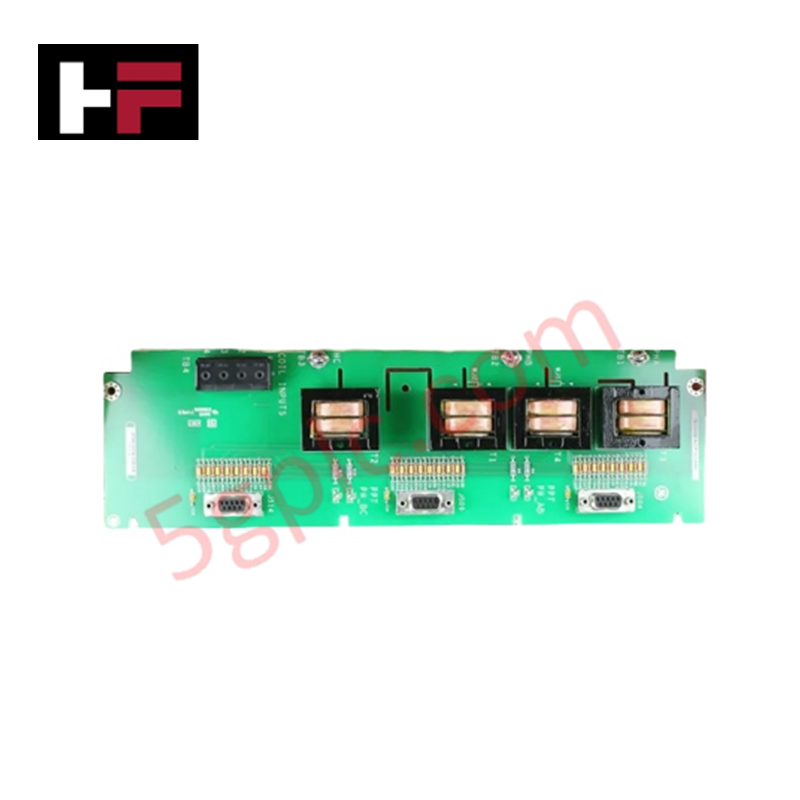
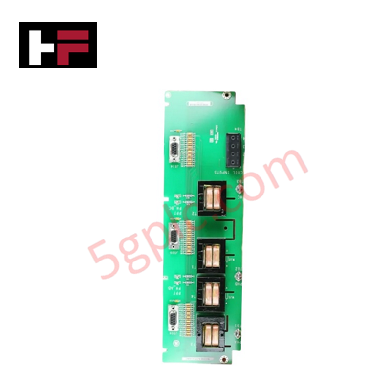
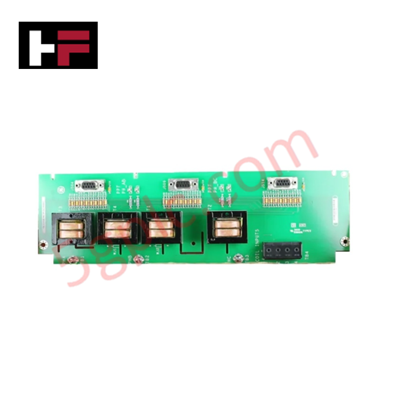
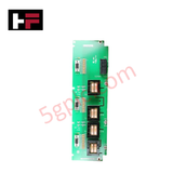
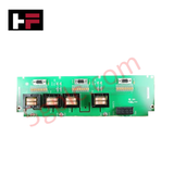
Configured for high-voltage sensing in EX2100 excitation control systems, the GE IS200EACFG1A (IS200EACFG1A Exciter AC Feedback Board) provides direct physical/electrical execution of exciter PPT supply voltage and current measurement.
Hardware Specifications
| Parameter | Specification |
|---|---|
| Model | IS200EACFG1A |
| Brand | General Electric |
| Origin | USA |
| Input Rating | 480 Vrms |
| Connectivity | 3 x DB9 (to M1, M2, C controllers) |
Profinet / EtherNet/IP Deterministic Networks
The IS200EACFG1A integrates three-phase voltage measuring transformers and dedicated terminals for two flux/air core coils to monitor excitation supply parameters. The board fans out these voltage and current circuits to three DB9 connectors, enabling synchronized signal transmission to the M1, M2, and C controllers. To maintain deterministic signal integrity over long-distance cable runs (up to 90 meters to the EBKP backplane), the hardware employs high-frequency noise reduction near the signal entrance points. Firmware flash compatibility and internal signal conditioning ensure precise feedback scaling, supporting reliable excitation regulation within the EX2100 system architecture.
Frequently Asked Questions
Q: Can the IS200EACFG1A be used for 1000 Vrms input applications?
A: No. The EACFG1 variant is specifically calibrated for 480 Vrms inputs. Use the EACFG2 model for 1000 Vrms or the EACFG3 model for 1300 Vrms requirements to prevent hardware damage and ensure measurement accuracy.
Q: How should cable shields be terminated on this board?
A: Cable shield terminal screws are provided on the board and must be connected to the cabinet chassis ground. These screws are located within three inches of the input terminals to minimize ground loop impedance and EMI susceptibility.
Field Installation Guidelines
- Mounting: Install the board within the exciter auxiliary cabinet. Ensure a secure mechanical bond to the chassis to facilitate effective shielding and grounding.
- Signal Wiring: Terminate voltage and flux/air core coil inputs using the provided terminal screws. Maintain short lead lengths for all signal wiring to minimize induced noise.
- Shielding: Terminate all signal cable shields to the designated chassis ground screws immediately at the input entry point. Do not extend shield drains beyond the provided terminal points.
- Controller Interfacing: Connect the three DB9 ports to the M1, M2, and C controllers using shielded industrial-grade serial cabling. Verify the 90-meter maximum length limit for connections linking the EACF to the EBKP backplane to ensure signal fidelity.
Additional Information
- 100% Genuine Parts: All products are original and authentic, ensuring reliable industrial performance.
- 30-Day Refund Guarantee: Return any in-stock item within 30 days in original, unopened packaging for a full refund (excluding shipping and fees).
- 12-Month Warranty: Covers defects in materials or workmanship; excludes misuse, normal wear, or unauthorized modifications.
- Worldwide Shipping: We ship via USPS, UPS, FedEx, and DHL. Delivery times vary by country and may be subject to customs or import fees.
- Support & Contact: Technical and warranty assistance is available anytime. Contact us here: Contact.
- Purchase Guidance: Check product specifications and compatibility carefully before ordering to ensure proper application.
Tech & Buying Guide

Navigating Industrial Automation Failures: Types, Causes, and Mitigation Strategies
Modern manufacturing relies heavily on automated control systems to maximize throughput and maintain product quality. However, unplanned downtime in industrial automation can cost facility operators thousands of dollars per hour. Understanding how programmable logic controllers (PLCs), distributed control systems (DCS), and field instrumentation fail empowers engineering teams to implement robust preventive maintenance strategies.

Essential Motion Control Commands: A Practical Guide for Engineers
Automation engineers often rely on precise position and speed control to drive modern factory machinery. Modern industrial systems, such as Programmable Logic Controllers (PLCs) and Distributed Control Systems (DCS), depend heavily on standardized motion instructions. Mastering these commands ensures operational safety, protects mechanical components, and optimizes cycle times across production lines.

The Role of Intrinsic Safety Barriers in PLC and DCS Architectures
Implementing robust protection in hazardous industrial environments represents a fundamental safety requirement in factory automation. Process facilities often handle volatile gases, dusts, and chemical agents that pose significant combustion risks. Consequently, control system engineers must deploy energy-limiting interfaces to isolate safe-area control cabinets from hazardous-area field instrumentation. This article examines the function, selection, and electrical principles of intrinsic safety barriers within modern PLC and DCS networks.