










Product Details
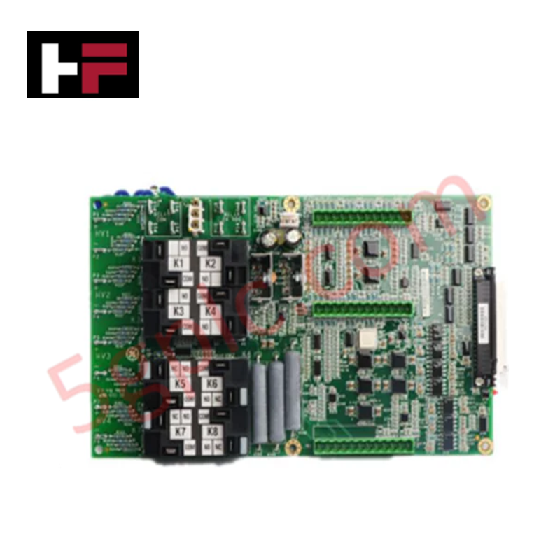
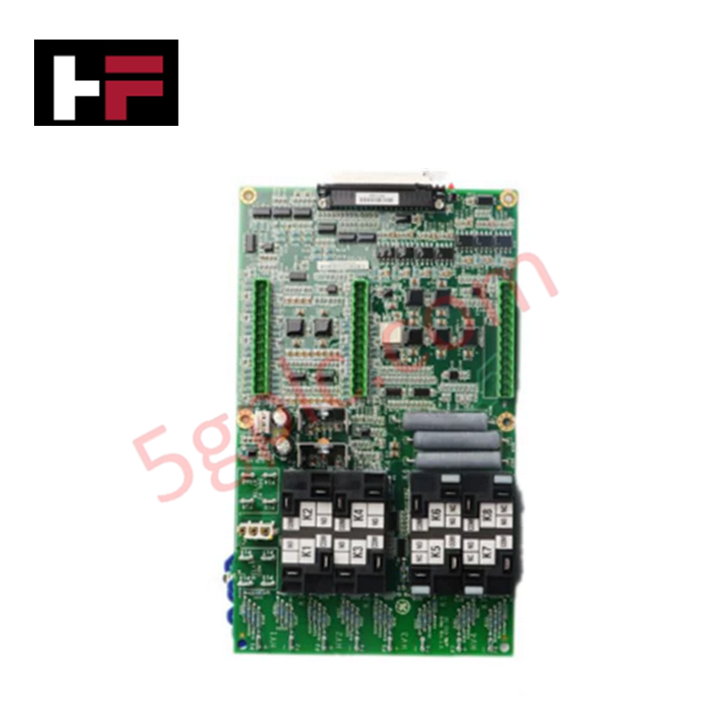
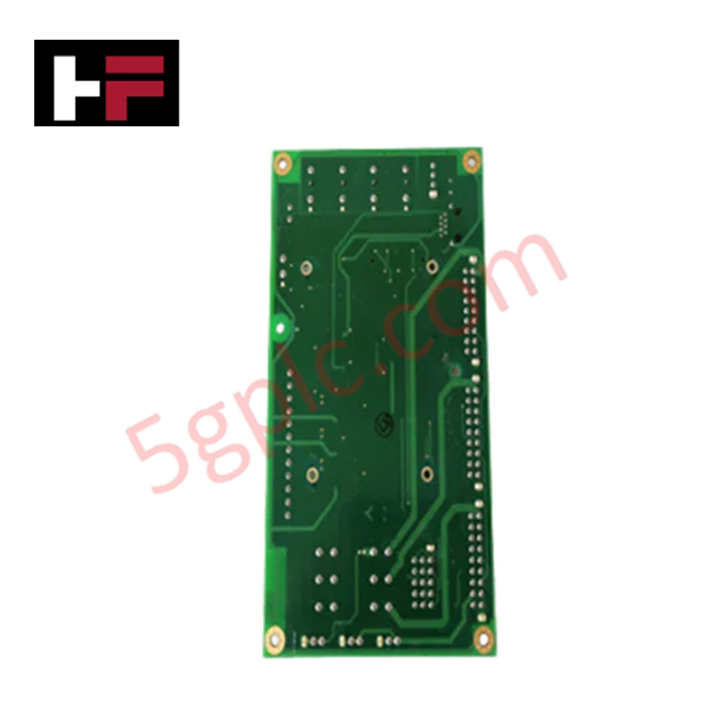
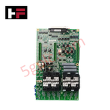
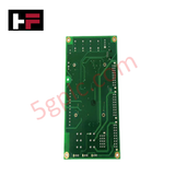
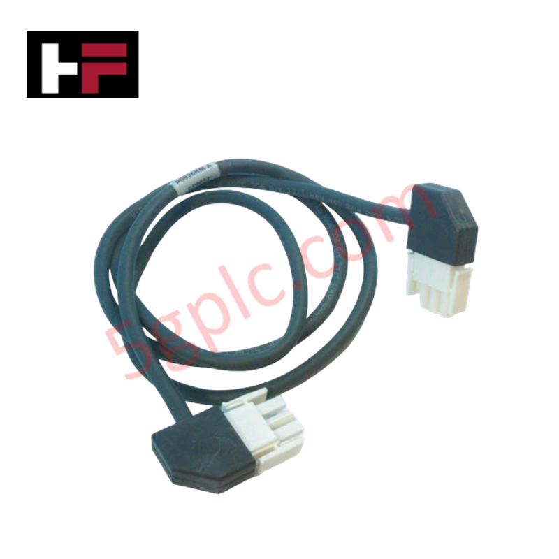
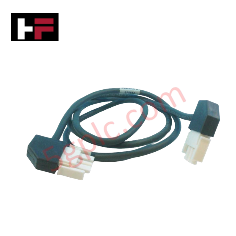
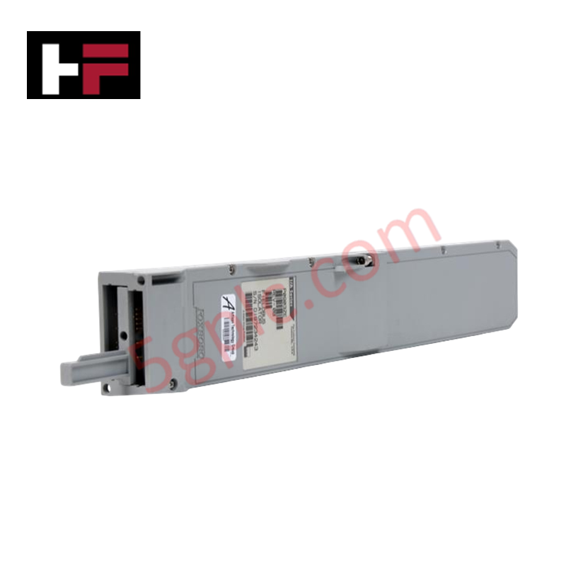
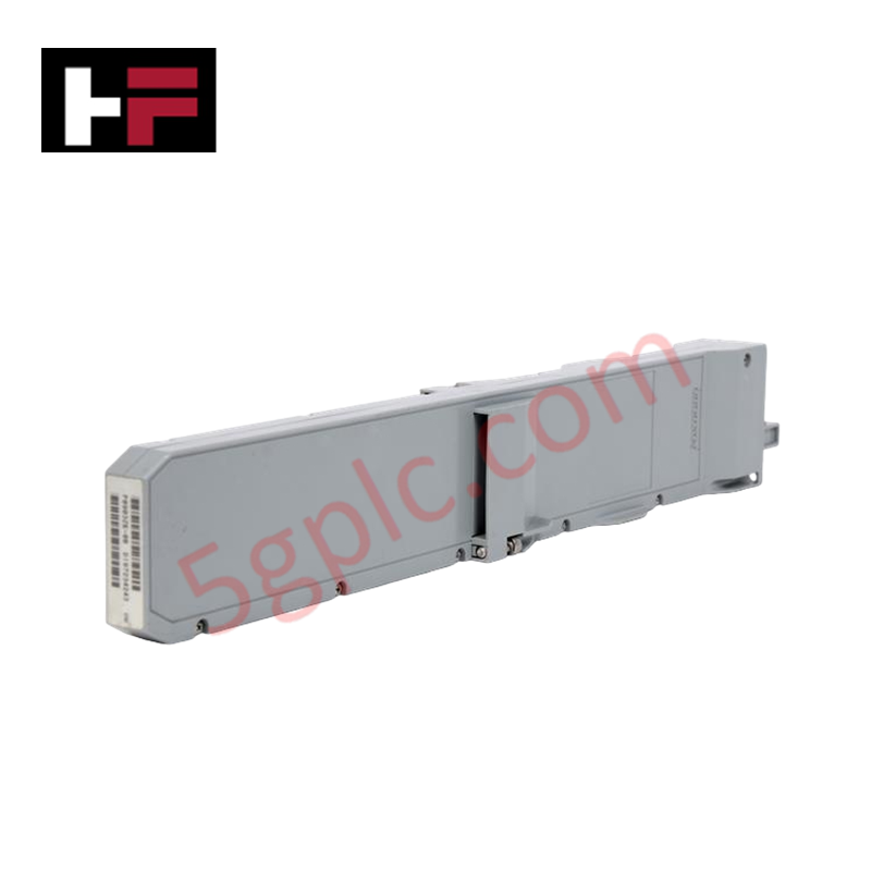
The GE IS210AEAAH1BGB, also cataloged as the IS210AEAA Communication Interface Board, operates as a dedicated hardware component for multi-channel data processing and system networking within Mark VI platforms.
Hardware Specifications
| Parameter | Specification |
|---|---|
| Model | IS210AEAAH1BGB |
| Brand | GE |
| Origin | USA |
| Weight | 1.2 kg |
| Dimensions | 350 x 250 x 60 mm |
| Operating Temp | -40 to 70 deg C |
| Power Consumption | 24 VDC nominal input |
| Output Voltage Range | 0 to 10 VDC maximum |
| Enclosure Protection | Rated NEMA 4 / IP65 |
| Vibration Limit | 5 g up to 2 kHz |
| Power Monitoring | Analog/digital status feedback via J301 backplane connector |
Backplane Bus Communication and Firmware Flash Compatibility
The IS210AEAAH1BGB operates on a VME architecture to interface main controllers with I/O cards and the IONet control network layer. The hardware routes parallel data streams between field circuitry and FPGA processing logic across multiple input and output channels. Power status signals route through the J301 backplane connector to enable continuous internal bus monitoring. Deterministic bus timings maintain operational synchronization across backplane slots, while underlying firmware flash compatibility supports reliable hardware handshaking during full-speed network transactions.
Frequently Asked Questions
Q: How does the board receive power status feedback from the system?
A: Analog and digital power supply monitoring signals are routed directly into the module through the J301 backplane connector interface.
Q: What network protocols or bus architectures does this module interface with?
A: The board interfaces via a VME backplane architecture, facilitating primary data transfer between main controllers, distributed I/O boards, and the IONet system network.
Q: Is hot-swapping supported for the IS210AEAAH1BGB during active rack operation?
A: Hot-swapping must follow strict Mark VI system procedures; power off the slot or ensure the VME bus section is isolated prior to module extraction to prevent backplane bus disruptions.
Field Installation Guidelines
Verify that all power supplies connected to the rack chassis are de-energized before inserting or removing the module. Align the board edges with the enclosure card guides and press firmly until the J301 backplane connector seats completely into the bus motherboard. Tighten faceplate securing screws to maintain chassis ground continuity and prevent mechanical dislodgement from high vibrations up to 5 g. Ensure field wiring cables maintain proper strain relief and are routed clear of high-voltage lines to minimize electromagnetic interference. Wear a grounded ESD wrist strap throughout the installation process to prevent static damage to sensitive FPGA components.
Additional Information
- 100% Genuine Parts: All products are original and authentic, ensuring reliable industrial performance.
- 30-Day Refund Guarantee: Return any in-stock item within 30 days in original, unopened packaging for a full refund (excluding shipping and fees).
- 12-Month Warranty: Covers defects in materials or workmanship; excludes misuse, normal wear, or unauthorized modifications.
- Worldwide Shipping: We ship via USPS, UPS, FedEx, and DHL. Delivery times vary by country and may be subject to customs or import fees.
- Support & Contact: Technical and warranty assistance is available anytime. Contact us here: Contact.
- Purchase Guidance: Check product specifications and compatibility carefully before ordering to ensure proper application.

Tech & Buying Guide

Transforming Shop Floor Data into Actionable Insights: A Deep Dive into MES
Manufacturing Execution Systems serve as the digital backbone of modern factory floors. Positioned at Level 3 of the ISA-95 automation pyramid, MES links enterprise resource planning with real-time shop floor control systems. Today, industrial operators rely on MES software to bridge operational strategy with physical production execution.

Managed Switch vs. Unmanaged Switch: Industrial Ethernet Architecture

Hot Standby vs. Cold Standby Redundancy in Industrial Automation
System availability determines process safety and productivity in industrial automation. Control engineers deploy redundancy to eliminate single points of failure. This technical guide evaluates Hot Standby vs. Cold Standby architectures, comparing failover speeds, memory sync, cost trade-offs, and field selection criteria.