












Product Details
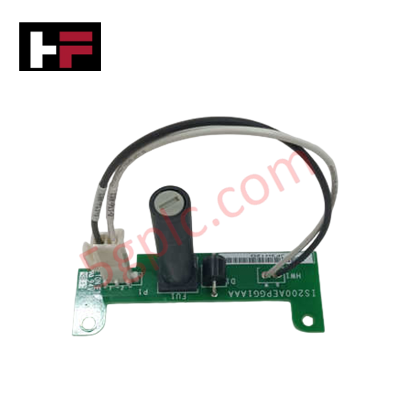
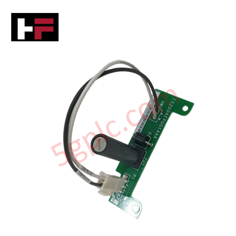
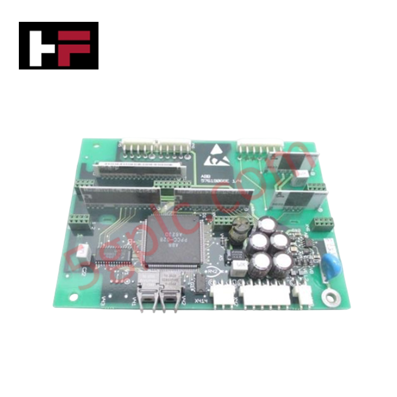
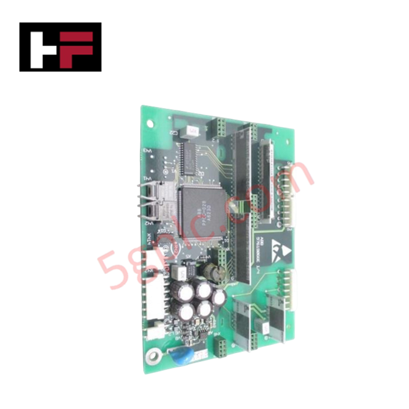
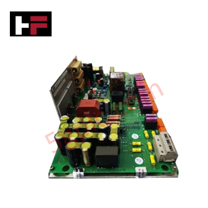
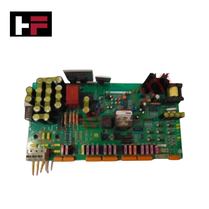
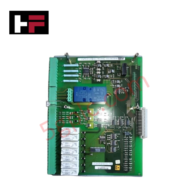
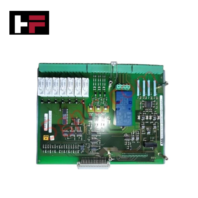
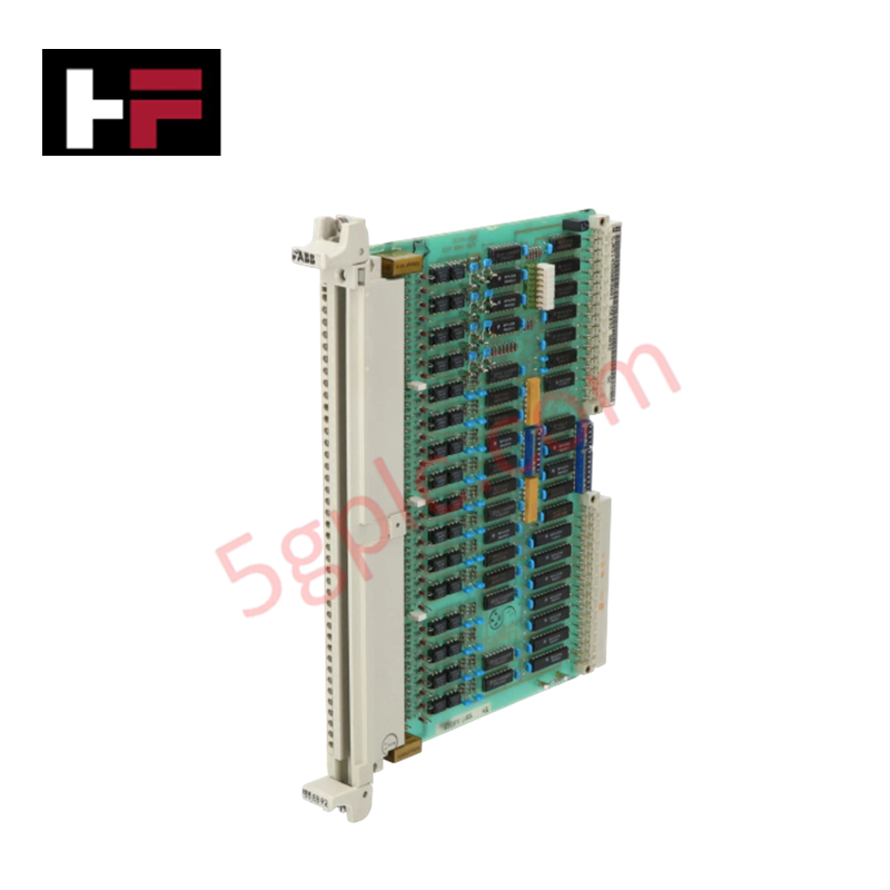
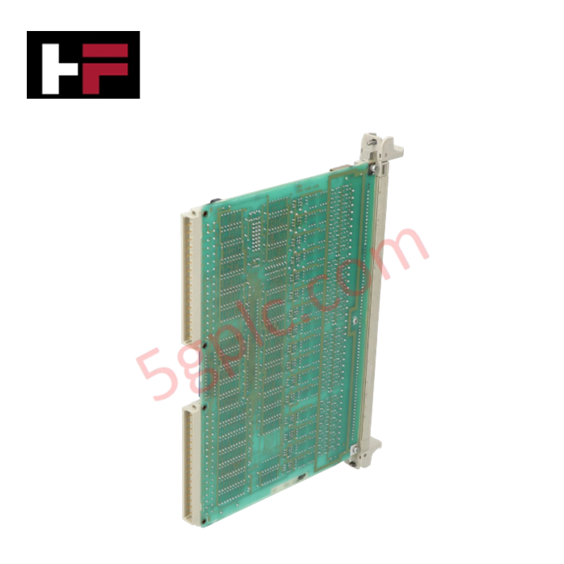
The GE IS200GDDDG1ABA, also cataloged as the IS200GDDDG1ABA Gate Driver and Dynamic Discharge Board, operates as a dedicated hardware component for signal isolation and IGBT control within EX2000 excitation systems.
Hardware Specifications
| Parameter | Specification |
|---|---|
| Model | IS200GDDDG1ABA |
| Brand | General Electric |
| Origin | USA |
| Weight | Standard PCB assembly |
| Dimensions | 17.8 cm x 33.02 cm |
| Operating Temp | -30 deg C to 65 deg C |
| Power Consumption | System-bus dependent |
| Primary Function | Gate drive and dynamic discharge control |
Backplane Bus Communication Velocity Licences
The IS200GDDDG1ABA serves as the interface between the primary processor firing circuits and the power-stage IGBTs. By providing localized interface isolation, the board facilitates consistent backplane bus communication velocity while preventing electrical noise injection from the high-power excitation circuit. Firmware flash compatibility is aligned with EX2000 system-level control parameters to ensure synchronized IGBT switching. The module manages I/O density scaling by overseeing the gating circuits for active IGBTs in both A and B legs, regulating activation and deactivation cycles to maintain precise PWM-based exciter performance.
Frequently Asked Questions
Q: Does the IS200GDDDG1ABA board support hot-swapping while the exciter is in operation?
A: No. The board must be de-energized and verified to a zero-energy state before removal to prevent unintended IGBT firing or damage to the gating circuits.
Q: How is the dynamic discharge circuit monitored?
A: The board provides direct control and monitoring over the dynamic discharge circuitry. Status feedback is propagated to the EX2000 primary processor to confirm activation state during discharge sequences.
Field Installation Guidelines
- Mounting: Secure the board within the EX2000 cabinet using the standard mounting hardware. Ensure the module is properly seated to maintain connection with the power-stage gating interface.
- Wiring: Verify all connections between the gate driver board and the A/B leg IGBT gate terminals. Use specified high-voltage-rated cable to minimize electromagnetic interference during high-speed switching.
- Grounding: Ensure the board chassis is bonded to the cabinet ground bus. Proper grounding is necessary to protect the isolation barrier between the firing circuits and the power stage.
- Environment: Maintain the cabinet ambient temperature between -30 deg C and 65 deg C. Ensure that the cooling profile for the excitation assembly is not obstructed to maintain IGBT thermal stability.
- Verification: Prior to startup, perform an offline test of the gate drive output pulses using the EX2000 diagnostic software to confirm correct signal propagation to the power switches.
Additional Information
- 100% Genuine Parts: All products are original and authentic, ensuring reliable industrial performance.
- 30-Day Refund Guarantee: Return any in-stock item within 30 days in original, unopened packaging for a full refund (excluding shipping and fees).
- 12-Month Warranty: Covers defects in materials or workmanship; excludes misuse, normal wear, or unauthorized modifications.
- Worldwide Shipping: We ship via USPS, UPS, FedEx, and DHL. Delivery times vary by country and may be subject to customs or import fees.
- Support & Contact: Technical and warranty assistance is available anytime. Contact us here: Contact.
- Purchase Guidance: Check product specifications and compatibility carefully before ordering to ensure proper application.
Tech & Buying Guide

Static UPS vs. Rotary UPS: Technical Evaluation for Industrial Automation

Comprehensive Guide to Noise Types in Industrial Automation and Electronics

Mitigating Emergency Stop Spurious Trips in Industrial Control Systems
Emergency stop (E-Stop) pushbuttons serve as vital safety devices in factory automation and process control plants. Functional safety standards mandate normally-closed (NC) contact blocks to ensure fail-safe operation during wiring breaks or power outages. However, mechanical degradation over time can trigger unexpected spurious trips, halting production lines without an actual emergency. Understanding the underlying causes of mechanical contact failure allows automation engineers to implement robust, fault-tolerant safety circuits.