











Product Details
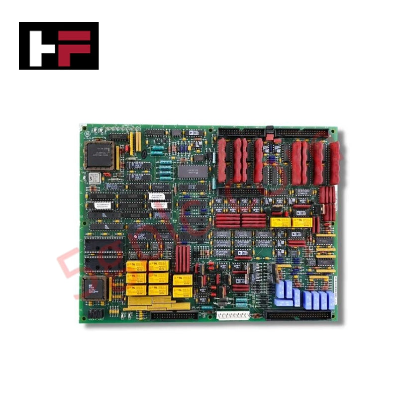
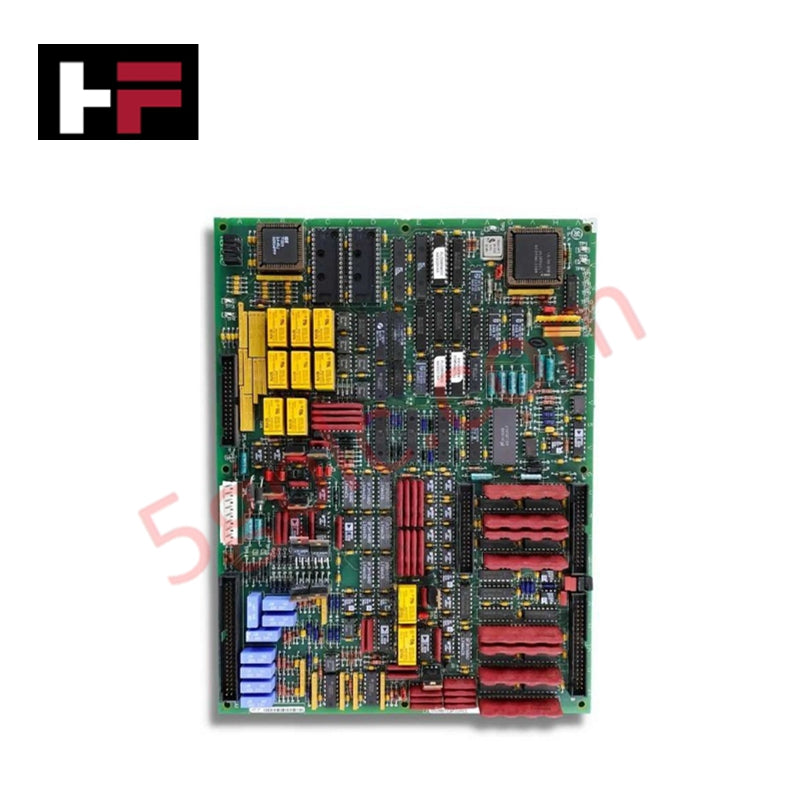
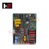
Configured for signal expansion and circuit regulation in Mark V turbine control systems, the GE DS200TCQFG1A (DS200TCQF Analog I/O Extension Card) provides direct physical execution of circuit switching and status monitoring.
Hardware Specifications
| Parameter | Specification |
|---|---|
| Model | DS200TCQFG1A |
| Brand | General Electric |
| Origin | USA |
| Operating Temp | Standard industrial range |
| Power Consumption | Not specified |
| Connectors | 2 x 50-pin (JUU, JB), 1 x 34-pin (JA), 1 x 9-pin |
| Status Indicators | 6 x Horizontal green LEDs |
Backplane Bus Communication and Deterministic Processing
The DS200TCQFG1A employs onboard electronic relays to facilitate circuit switching during routine processing cycles. These relays utilize soldered wire leads to maintain mechanical connection stability within the board assembly. The module interfaces with the control cabinet backplane via a 34-pin connector (JA) and two 50-pin connectors (JUU, JB). Deterministic I/O status is verified through 6 horizontally positioned LEDs, which illuminate green when power is applied and the respective logic functions are operating within nominal parameters. These indicators serve as the primary diagnostic interface for verifying backplane bus communication velocity and operational status during active processing.
Frequently Asked Questions
Q: Are the soldered relay wire leads field-replaceable?
A: No. The relays and their wire leads are factory-soldered to the PCB assembly. Attempting to repair or replace these components in the field risks damaging the circuit traces and compromising the structural integrity of the board.
Q: What is the significance of the 6 green LEDs on the board face?
A: Each LED corresponds to a specific I/O function or power rail. A green, illuminated LED indicates that the assigned function is receiving power and operating within normal design limits. If an LED is dark, it signals a loss of power or a failure in the corresponding circuit.
Field Installation Guidelines
- Ensure the Mark V control rack is de-energized before inserting the DS200TCQFG1A card to prevent electrical transients from damaging the I/O connectors.
- Verify that all 50-pin and 34-pin cable assemblies are correctly oriented and fully seated in their respective ports (JUU, JB, JA) to ensure reliable signal transmission.
- Handle the board by its edges or faceplate to protect the soldered relay leads from mechanical stress and to prevent electrostatic discharge damage.
- After installation, observe the horizontal LED array; all 6 LEDs must be green to confirm correct power distribution and functional synchronization with the drive control system.
Additional Information
- 100% Genuine Parts: All products are original and authentic, ensuring reliable industrial performance.
- 30-Day Refund Guarantee: Return any in-stock item within 30 days in original, unopened packaging for a full refund (excluding shipping and fees).
- 12-Month Warranty: Covers defects in materials or workmanship; excludes misuse, normal wear, or unauthorized modifications.
- Worldwide Shipping: We ship via USPS, UPS, FedEx, and DHL. Delivery times vary by country and may be subject to customs or import fees.
- Support & Contact: Technical and warranty assistance is available anytime. Contact us here: Contact.
- Purchase Guidance: Check product specifications and compatibility carefully before ordering to ensure proper application.


Tech & Buying Guide

Mastering Wire Identification in Industrial Automation: The Power of Ferrules and Cross-Ferruling
Proper wire labeling forms the cornerstone of reliable control system installation and long-term maintenance. In complex industrial automation environments, technicians terminate thousands of conductor ends inside control panels, marshalling racks, and field junction boxes. Ferrules serve as individual tube-shaped sleeve markers slipped onto conductors before final termination. While technicians historically relied on pre-printed individual letter rings, modern control panel builders utilize automated ferrule printing machines. These thermal-transfer printers generate durable, single-sleeve heat-shrink tags directly matching approved wiring schematics, significantly accelerating cabinet assembly workflows.

Understanding Marshalling Cabinets in Industrial Automation and Control Systems
Marshalling cabinets serve as the crucial connection hub between field instruments and centralized processing units. In large DCS and PLC control system architectures, hundreds of multipair field cables run from local junction boxes to the central instrument equipment room. The marshalling cabinet houses field terminal blocks, surge arresters, intrinsic safety isolation barriers, and interposing relays. By segregating field field-wiring terminations from sensitive processor hardware, engineers protect expensive controller backplanes from high-voltage transients. Consequently, this modular separation dramatically streamlines maintenance workflows and simplifies system expansion.

Essential Best Practices for PLC Wiring and Installation in Industrial Automation
Successful control system deployment begins with thoroughly reviewing manufacturer technical documentation. Controllers from major brands like Allen-Bradley, Siemens, and Schneider Electric feature unique terminal layouts. Engineers must verify voltage requirements before connecting power cables to prevent catastrophic equipment damage. Standard line connections require strict adherence to regional electrical codes and proper wire color coding. Furthermore, panel builders should always establish a robust low-impedance ground connection using at least 16-AWG copper conductor tied directly to the main plant grounding grid.