










Product Details
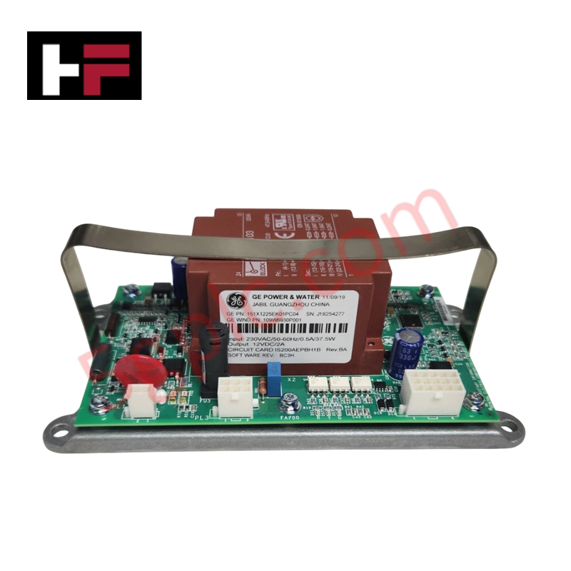
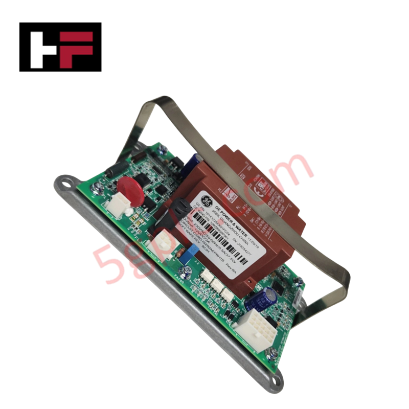
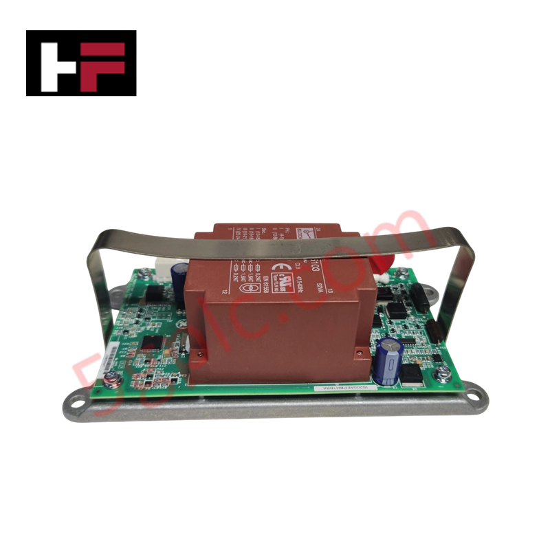
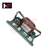
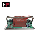
Configured for power conversion management and diagnostics within industrial control networks, the GE 151X1225EK01PC04 (151X1225EK Charger Card Circuit Board Assembly) provides direct physical/electrical execution.
Hardware Specifications
| Parameter | Specification |
|---|---|
| Model | 151X1225EK01PC04 |
| Brand | General Electric (GE Power & Water) |
| Origin | United States |
| Weight | Standard Rack Component Weight |
| Dimensions | Standard GE Control Board Footprint |
| Operating Temp | 0 - 60 deg C |
| Power Consumption | Load and Application Dependent |
| Input Voltage | Specific DC Voltage Input |
| Sub-Assembly Type | Charger Card Control Board Assembly |
| Insertion Style | Internal Rack or Enclosure Slot Mount |
Firmware Flash Compatibility and Internal Bus Synchronization
The circuit board assembly regulates DC charging parameters and monitors analog threshold points across dedicated backplane monitoring channels. Real-time data processing requires strict firmware flash compatibility across peripheral logic devices to ensure timing synchronization with the upstream master processor. This eliminates communication packet collision and structural latency across the internal bus structures, locking channel update profiles to deterministic system clock edges.
Frequently Asked Questions
Q: Does the 151X1225EK01PC04 assembly support live hot-swapping procedures?
A: No. The edge connectors on the 151X1225EK01PC04 board do not incorporate staggered trace lengths for sequential ground connection. Seating or extracting the card under active voltage loops can generate transient voltage spikes, resulting in permanent damage to logic components.
Q: How is the reference ground potential isolated on this board?
A: The board topology uses localized common isolation paths between low-voltage processing circuitry and the high-power charger lines. This structural separation prevents field-induced power surges from shifting the core logic zero-reference point.
Field Installation Guidelines
- Backplane Connector Alignment: Verify that all card edge slot pathways inside the enclosure are clear of conductive debris. Align the board assembly horizontally along the tracks and slide directly backward until the card pins engage firmly with the host receiver receptacle.
- Static Discharge Suppression: Always utilize a grounded static-dissipative wrist strap linked directly to the enclosure chassis prior to removing the card from its protective ESD shielding envelope.
- Ambient Thermal Clearing: Ensure neighboring modules or structural wire management paths do not obstruct natural convective airflow around the components to maintain junction temperature thresholds within the specified 0 - 60 deg C boundaries.
Additional Information
- 100% Genuine Parts: All products are original and authentic, ensuring reliable industrial performance.
- 30-Day Refund Guarantee: Return any in-stock item within 30 days in original, unopened packaging for a full refund (excluding shipping and fees).
- 12-Month Warranty: Covers defects in materials or workmanship; excludes misuse, normal wear, or unauthorized modifications.
- Worldwide Shipping: We ship via USPS, UPS, FedEx, and DHL. Delivery times vary by country and may be subject to customs or import fees.
- Support & Contact: Technical and warranty assistance is available anytime. Contact us here: Contact.
- Purchase Guidance: Check product specifications and compatibility carefully before ordering to ensure proper application.


Tech & Buying Guide

Demystifying CPU Communication Ports in Siemens PLC Architectures
Industrial automation relies heavily on robust data exchange between devices. Without seamless connectivity, field instruments, network switches, human-machine interfaces, and programmable logic controllers cannot coordinate effectively. Therefore, understanding the various CPU communication ports available in Siemens hardware ensures efficient factory automation design and seamless system integration.

Mastering the Siemens PLC Scan Cycle: How the CPU Executes Automation Programs
Industrial automation relies heavily on programmable logic controllers (PLCs) to manage complex manufacturing processes. Many engineers dive straight into programming without mastering the underlying architecture. However, understanding how a PLC CPU executes a program ensures reliable system design. Therefore, mastering the scan cycle optimizes both performance and troubleshooting in modern control systems.

How to Connect to Siemens S7 PLCs: 5 Essential Communication Methods
Establishing a reliable hardware link between a programming terminal and a Siemens SIMATIC controller is essential for engineering workflows. Field engineers rely on distinct physical layers, ranging from legacy serial connections to high-speed Industrial Ethernet protocols. Modern factory automation environments prioritize fast data transfer and seamless driver integration. Selecting the correct connection method simplifies program downloads, online monitoring, and system troubleshooting in complex control systems.