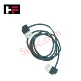
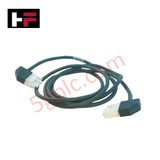
Product Details
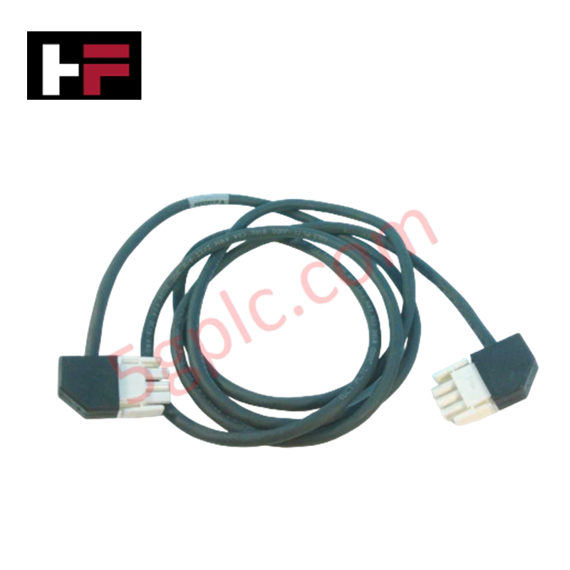
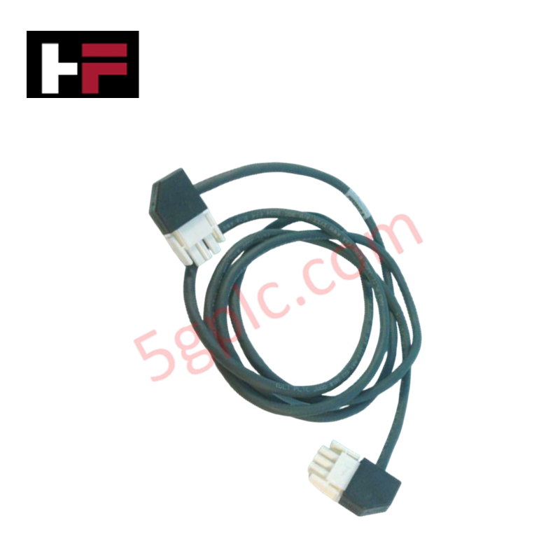
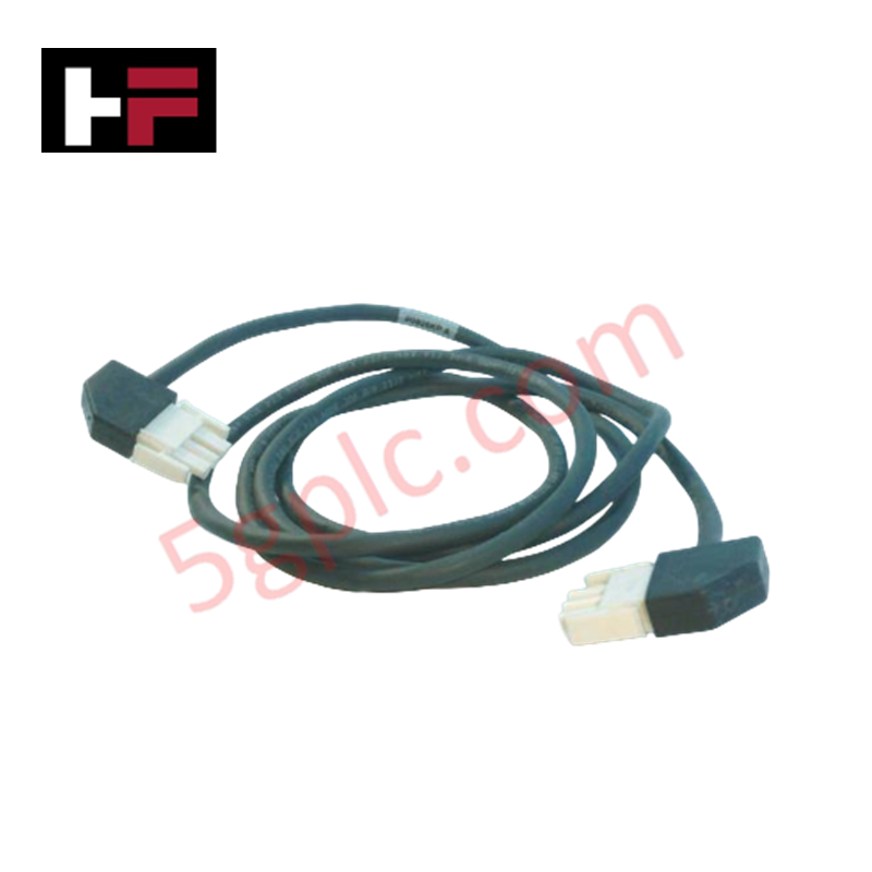
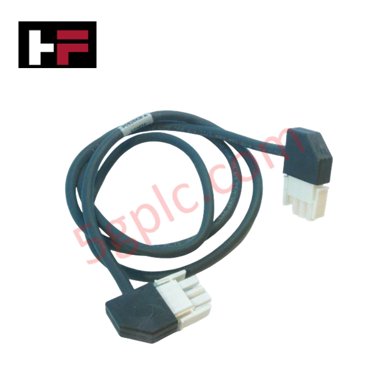
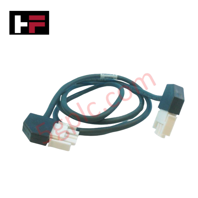
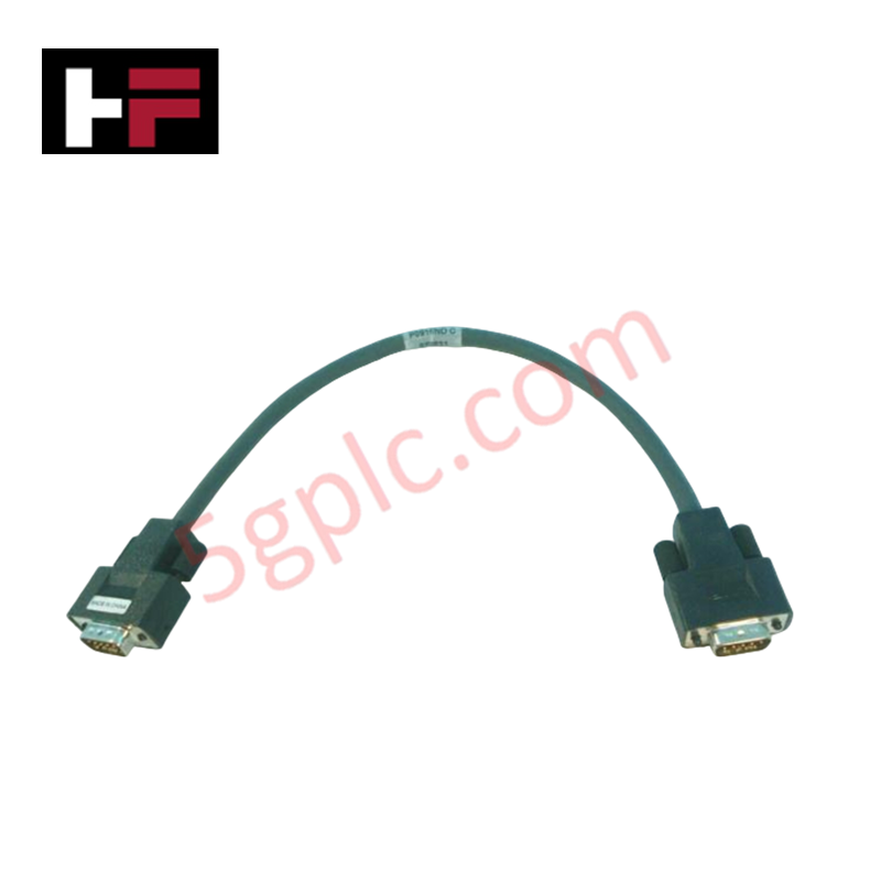
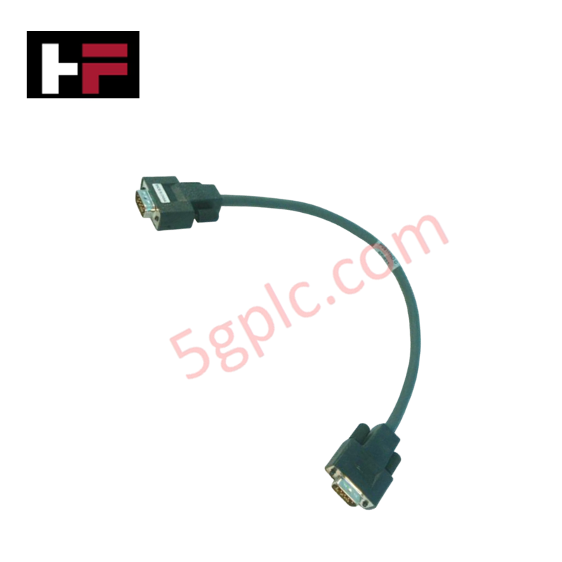
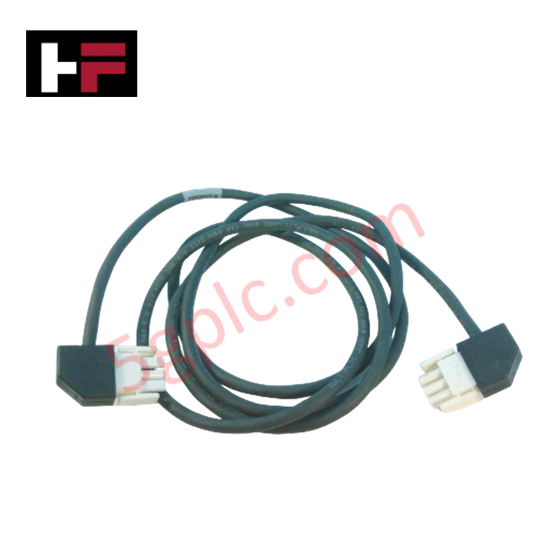
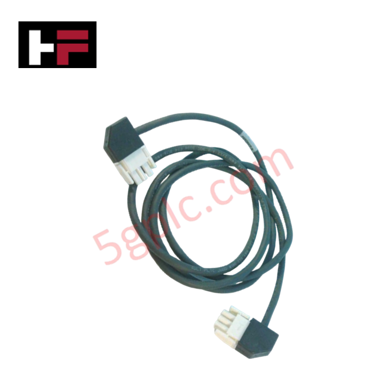
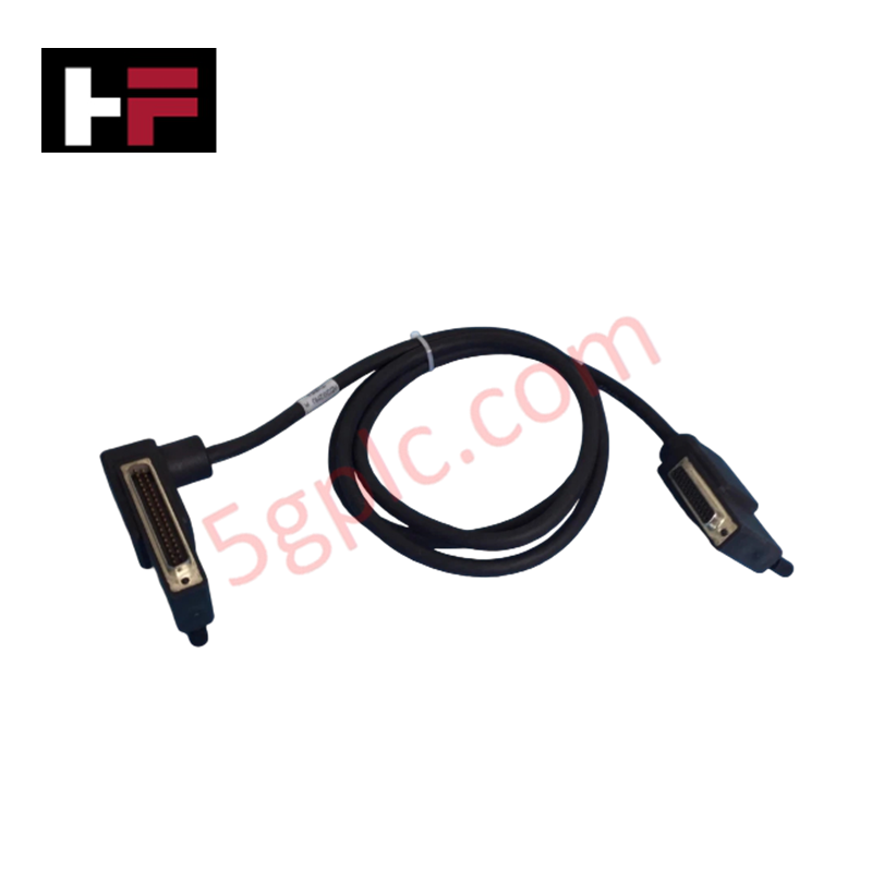
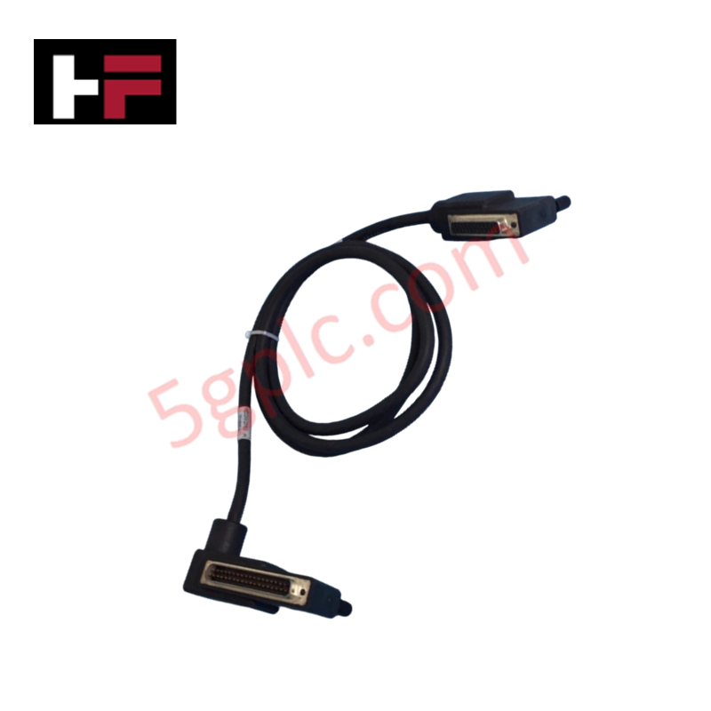
The Foxboro P0923DC, also cataloged as the P0923DC Status Alarm Cable, operates as a dedicated hardware component for diagnostic relay signaling and power supply health monitoring within Foxboro I/A Series control system enclosure assemblies. Configured with factory-terminated connectors and multi-conductor shielded copper wiring, this cable interfaces internal power supply alarm relay contacts directly to control module backplanes and system monitor cards to transmit discrete fault status signals.
Hardware Specifications
| Parameter | Specification |
|---|---|
| Model | P0923DC |
| Brand | Foxboro |
| Origin | USA |
| Weight | ~0.25 kg (~0.55 lbs) |
| Dimensions | Standard Prefabricated Assembly Length |
| Operating Temp | 0 to +60 deg C (32 to 140 deg F) |
| Power Consumption | Passive Component (Zero active power drain) |
| Signal Type | Discrete Status / Alarm Contact Sense |
| Shielding | Overall Braided Foil Shield with Drain Wire |
| Connector Type | Multi-pin Polarized Headers |
DCS Process Control and Signal Isolation
The Foxboro P0923DC cable transfers critical power module status signals, including input AC loss, output DC under-voltage, and thermal trip alarms, to central system controllers without introducing ground loops. Integrated channel-to-channel isolation and overall shield grounding protect small-signal discrete logic lines from adjacent high-voltage AC cables and electromagnetic interference (EMI). By maintaining galvanic separation between diagnostic sensing circuits and main backplane logic pathways, the cable ensures reliable fault detection and alarm propagation across Foxboro DCS architectures.
Frequently Asked Questions
Q: Can the Foxboro P0923DC cable be disconnected or connected while the DCS rack is powered?
A: Yes, as a passive discrete signaling cable operating on low-voltage logic sensing circuits, it can be safely disconnected without disrupting main DC power delivery, though an active diagnostic alarm will trigger on the host controller during disconnection.
Q: What pin continuity checks should be performed during routine maintenance of the cable?
A: Verify end-to-end electrical continuity across each conductor core, confirm shield ground continuity at the designated ground tab, and ensure open-circuit resistance between individual signal lines.
Field Installation Guidelines
- Inspect the cable outer jacket and molded connector strain reliefs for cracks, cut insulation, or bent contact pins prior to installation.
- Route the cable through designated cabinet wireways, ensuring it maintains a minimum clearance from high-voltage AC power lines to minimize EMI coupling.
- Align keyway slots on the polarized multi-pin connectors with the power supply status header and push until retention latches lock securely.
- Terminate the integral shield drain wire to the central cabinet earth ground bar according to standard DCS grounding practices.
Additional Information
- 100% Genuine Parts: All products are original and authentic, ensuring reliable industrial performance.
- 30-Day Refund Guarantee: Return any in-stock item within 30 days in original, unopened packaging for a full refund (excluding shipping and fees).
- 12-Month Warranty: Covers defects in materials or workmanship; excludes misuse, normal wear, or unauthorized modifications.
- Worldwide Shipping: We ship via USPS, UPS, FedEx, and DHL. Delivery times vary by country and may be subject to customs or import fees.
- Support & Contact: Technical and warranty assistance is available anytime. Contact us here: Contact.
- Purchase Guidance: Check product specifications and compatibility carefully before ordering to ensure proper application.
Tech & Buying Guide

Managed Switch vs. Unmanaged Switch: Industrial Ethernet Architecture

Hot Standby vs. Cold Standby Redundancy in Industrial Automation
System availability determines process safety and productivity in industrial automation. Control engineers deploy redundancy to eliminate single points of failure. This technical guide evaluates Hot Standby vs. Cold Standby architectures, comparing failover speeds, memory sync, cost trade-offs, and field selection criteria.