Product Details
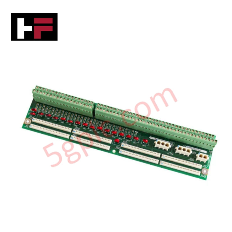
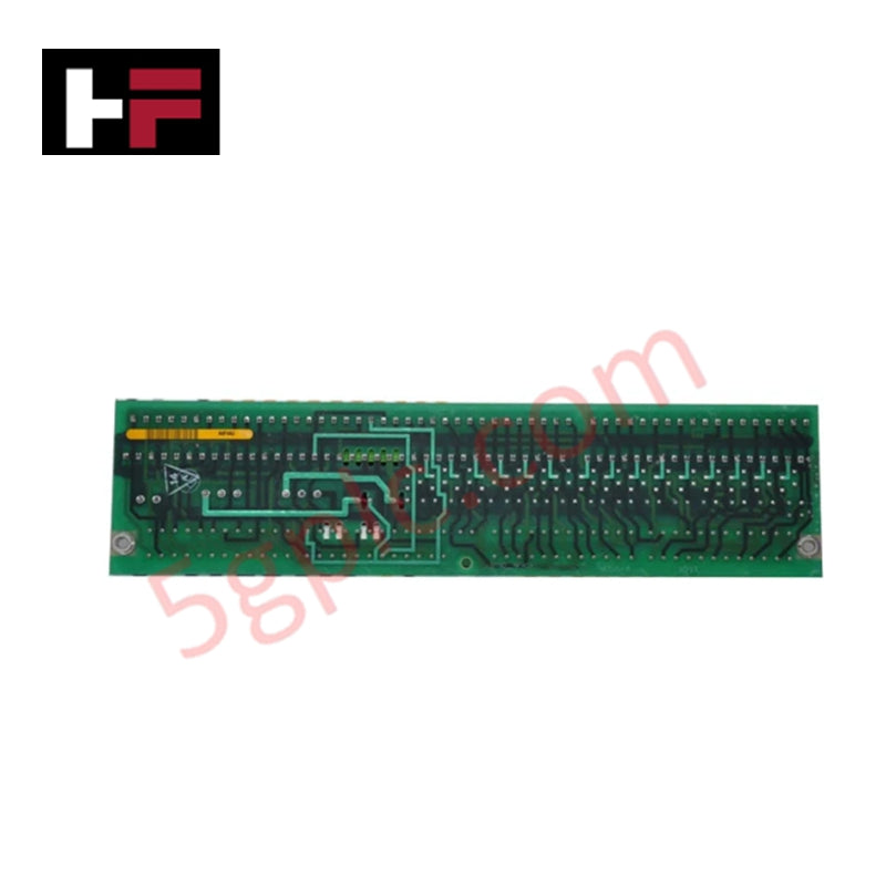
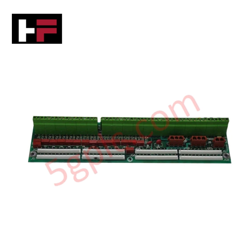
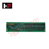
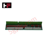
The GE DS200DTBDG1A serves as the primary DS200DTBD Contact Output Expansion Termination Module utilized to execute high-density field relay termination and voltage distribution across Mark V platforms.
Hardware Specifications
| Parameter | Specification |
|---|---|
| Model | DS200DTBDG1A |
| Brand | GE General Electric |
| Origin | USA |
| Operating Temp | Standard industrial range |
| Terminal Blocks | 2 blocks (107 terminals per block, 214 total) |
| Onboard Connectors | 3 x 34-pin (J8, J19, J20), 8 x Relay signal connectors (JS1-JS8) |
| Hardware Jumpers | 2 |
| Surface Protection | Conformal coating |
Deterministic Networks & I/O Density Scaling
The DS200DTBDG1A is engineered for high-capacity physical signal distribution within Mark V turbine control architectures. To accommodate complex control loop requirements, the module achieves I/O density scaling through two massive onboard terminal blocks, providing a continuous landing interface of 214 discrete wire points. Signal routing deterministic performance is governed by direct hardware bus linkages: eight specialized connectors (JS1 through JS8) interface directly with the TCRA relay board to acquire real-time contact commands. Concurrently, three 34-pin ribbon headers manage high-voltage physical execution, routing 125 VDC output power across contacts 47 and 48 via J19 and J20, while J8 establishes direct solenoid power distribution from the TCPD board. Firmware flash compatibility is not applicable to this passive termination assembly, as operational logic is governed strictly by hardwired traces and two field-configurable jumpers.
Frequently Asked Questions
Q: Can diagnostic test points TP1 and TP2 be probed during active turbine operation?
A: Probing onboard test points (TP1, TP2, etc.) during live operation is restricted to qualified technical personnel using calibrated, high-impedance test equipment. Improper grounding or probe slipping across adjacent high-density traces can induce false relay switching or short the 125 VDC bus.
Q: Is the DS200DTBDG1A electrically backward compatible with the base DS200DTBDG1 board?
A: Yes, the "A" functional revision represents a circuitry-enhancing PCB layout modification. It maintains direct backward compatibility for physical mounting and connector pinouts (J8, J19, J20, and JS1-JS8) when replacing unrevised parent boards.
Field Installation Guidelines
- Completely de-energize the Mark V cabinet power distribution system, specifically verifying zero potential on the 125 VDC supply lines routed to headers J19 and J20, before initiating board extraction or seating.
- Maintain strict electrostatic discharge (ESD) mitigation protocols. Ground the chassis and handle the PCB exclusively by its non-conductive edges to prevent degradation of the factory-applied conformal coating.
- Due to the extreme landing density of 214 terminals across two blocks, verify that all field signal wires are properly stripped, fitted with insulated ferrules, and torqued to standard industrial limits to prevent stray strand shorting.
- Securely route and lock the eight TCRA ribbon cables into headers JS1 through JS8, ensuring cable shielding is continuously grounded to the cabinet earth bar to suppress electromagnetic cross-talk.
Additional Information
- 100% Genuine Parts: All products are original and authentic, ensuring reliable industrial performance.
- 30-Day Refund Guarantee: Return any in-stock item within 30 days in original, unopened packaging for a full refund (excluding shipping and fees).
- 12-Month Warranty: Covers defects in materials or workmanship; excludes misuse, normal wear, or unauthorized modifications.
- Worldwide Shipping: We ship via USPS, UPS, FedEx, and DHL. Delivery times vary by country and may be subject to customs or import fees.
- Support & Contact: Technical and warranty assistance is available anytime. Contact us here: Contact.
- Purchase Guidance: Check product specifications and compatibility carefully before ordering to ensure proper application.


Tech & Buying Guide

Importance of Safety Barriers in PLC and DCS Control Systems

Static UPS vs. Rotary UPS: Technical Evaluation for Industrial Automation